Variable-speed driving system

A technology of variable speed drive and deceleration transmission, applied in the field of vehicle wheel hub and two-stage variable speed drive system, can solve the problems of energy-consuming and time-consuming, and achieve the effect of compact structure, improved reliability, and optimized structure setting.

Active Publication Date: 2018-03-16
ROBERT BOSCH GMBH
View PDF6 Cites 2 Cited by
  • Summary
  • Abstract
  • Description
  • Claims
  • Application Information

AI Technical Summary

Problems solved by technology

This switching process is energy and time consuming

Method used


Image

  • Variable-speed driving system
  • Variable-speed driving system
  • Variable-speed driving system

Examples


Embodiment Construction

[0027] In the following detailed description, reference is made to the accompanying drawings, which form a part of this specification. In the drawings, identical or similar reference numbers typically identify identical or similar components, unless the text indicates otherwise. The embodiments described in the detailed description and drawings are not meant to be limiting. Other embodiments may be utilized and other changes may be made without departing from the spirit and / or scope of the invention. It should be understood that the aspects of the invention generally described in this specification and shown in the drawings can be arranged, replaced, combined, separated and designed in various configurations.

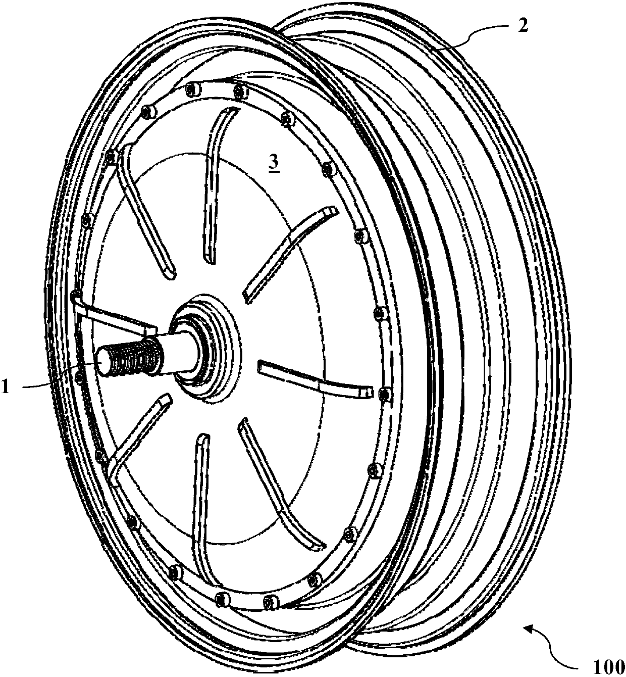
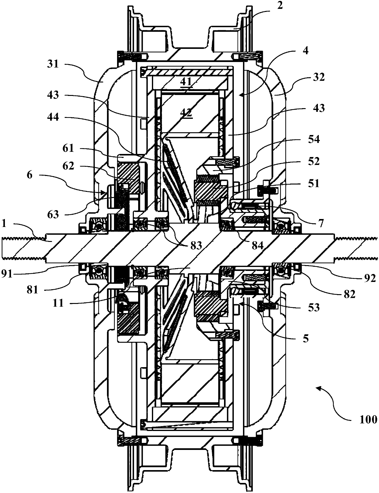
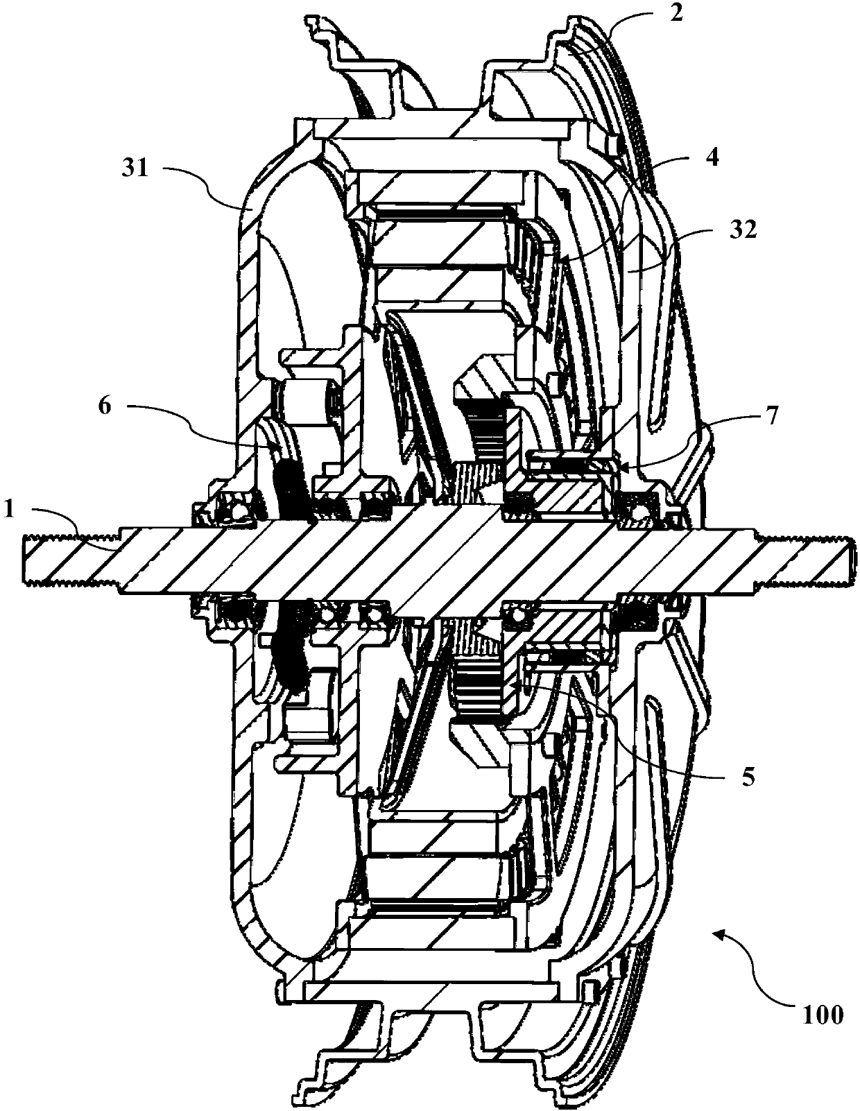
[0028] figure 1 A schematic perspective view of a variable speed drive system 100 according to the invention is shown. figure 2 show figure 1 A schematic longitudinal section view of a variable speed drive system 100, image 3 show figure 2 A vertical cross-sect...


PUM


Abstract

The invention relates to a variable-speed driving system (100). The variable-speed driving system (100) comprises a shaft (1), a rim (2) surrounded around the shaft, a cover (3), a motor (4), a speedreduction transmission device, a first clutch (7) and a second clutch (6), wherein the cover (3) comprises a first cover part (31) and a second cover part (32), and the first cover part and the secondcover part are fixedly connected with the rim; the motor (4) comprises a stator (42) and a rotor (41); the input side of the speed reduction transmission device is fixedly connected with the rotor; the first clutch (7) is arranged and used for enabling the output side of the speed reduction transmission device to be engaged with the second cover part; the second clutch (6) is arranged and used for enabling the rotor to be engaged with the first cover part (31); the motor, the speed reduction transmission device, the first clutch and the second clutch are contained in an inner chamber definedby the rim and the cover and are borne on the shaft, wherein the speed reduction transmission device is a planetary gear transmission device (5).

Description

technical field [0001] The present invention generally relates to a variable speed drive system, and more particularly to a two-stage variable speed drive system, especially for a wheel hub of a vehicle. Background technique [0002] A hub motor is a known electric motor for driving electric vehicles or motorcycles. Compared with traditional vehicles, the use of hub motors can save a large number of transmission components and greatly simplify the mechanical structure. Since the in-wheel motor has the characteristic of independent driving of a single wheel, various driving modes can be realized and improved driving flexibility can be obtained. As new energy vehicles are gaining more and more attention, in-wheel motors can also usually be used in electric vehicles or hybrid vehicles to achieve functions such as drive, power assist, and energy recovery. In addition, in-wheel motors are also widely used in electric motorcycles. [0003] Existing hub motors are mainly divided...

Claims


Application Information

Patent Timeline
Patent Type & Authority Applications(China)
IPC IPC(8): B60K17/02B60K7/00B60K17/08H02K7/116H02K5/10H02K7/10
CPCH02K5/10H02K7/10H02K7/116B60K7/0007B60K17/02B60K17/046B60K17/08Y02T10/64
Inventor 朱涛李维亚黄启林
Owner ROBERT BOSCH GMBH
Why Eureka
Try Eureka