De-allocation command processing acceleration method and storage device
A de-allocation and command technology, applied in the storage field, can solve problems such as prolonging the processing time of de-allocation commands, affecting the performance of solid-state drives, and affecting the execution of IO commands.
- Summary
- Abstract
- Description
- Claims
- Application Information
AI Technical Summary
Problems solved by technology
Method used
Image
Examples
Embodiment 1
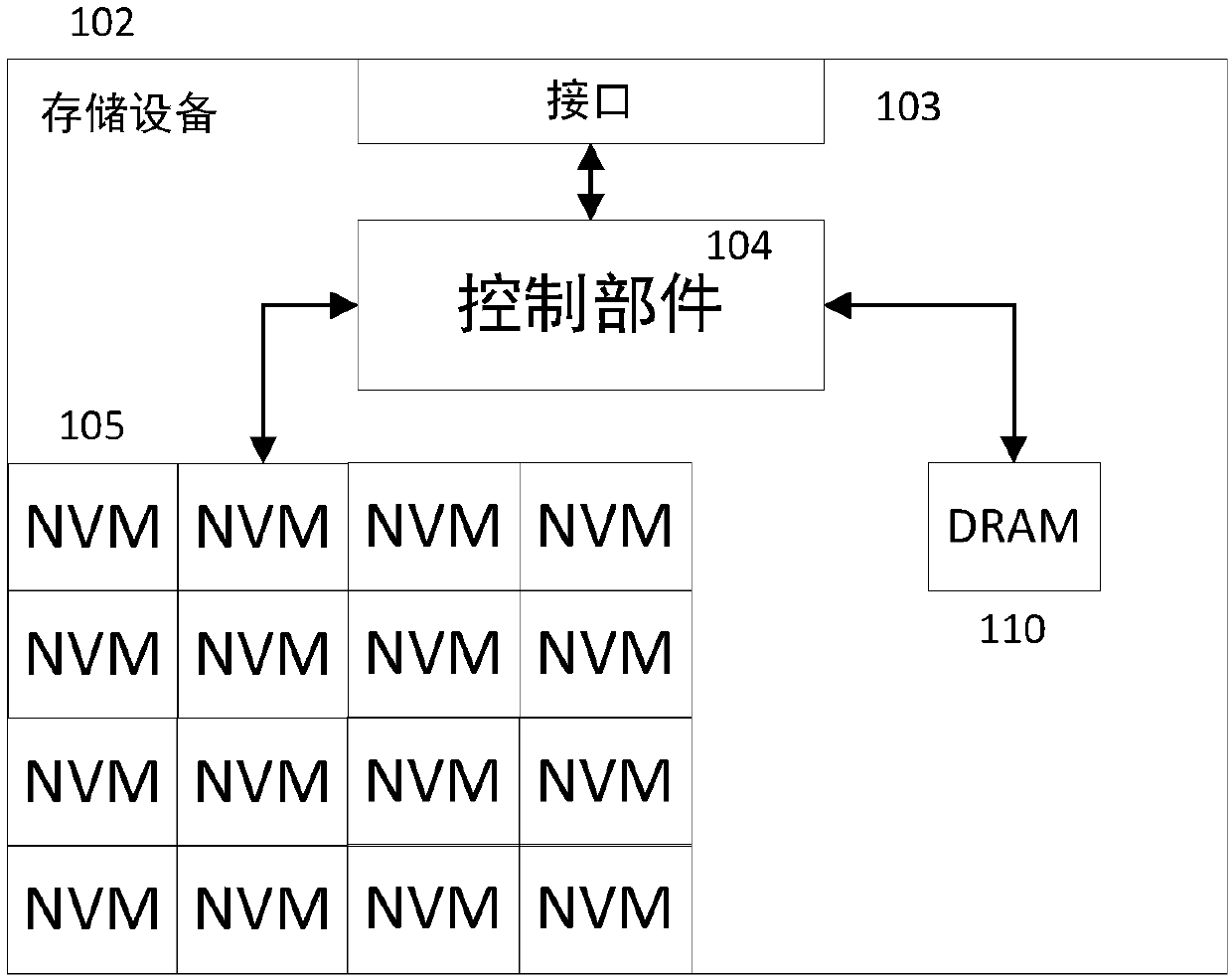
[0080] A table structure that stores mapping information from logical addresses to physical addresses is called an FTL table. The FTL table is important metadata in solid-state storage devices. The FTL table records the address mapping relationship in units of data pages in the storage device. The FTL table includes entries (or entries) of multiple FTL tables. In an example, the entry of each FTL table records the correspondence between a logical page address and a physical page. In another example, the entries of each FTL table record the corresponding relationship between multiple consecutive logical page addresses and multiple consecutive physical pages. In yet another embodiment, the entry of each FTL table records the correspondence between the logical block address and the physical block address. In yet another example, the FTL table records the mapping relationship between the logical block address and the physical block address, and / or the mapping relationship betwe...
Embodiment 2
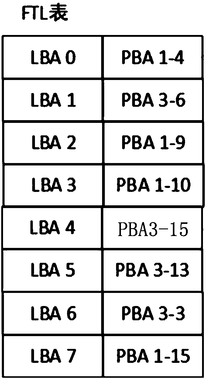
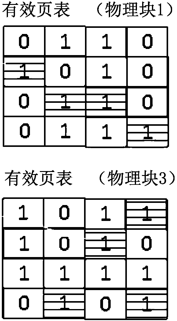
[0085] In this embodiment, an erasing or garbage collection operation is performed in units of physical blocks in the storage device. In this embodiment, the entry of each FTL table records the correspondence between a logical page address and a physical page. In the solid-state disk, an FTL table, a valid page table, and a valid page count table are maintained. in, figure 2 It is a schematic diagram of the FTL table before processing the de-allocation command in this embodiment, and the FTL table indicates the corresponding relationship between the logical page address and the physical page address. image 3 A schematic diagram of the valid page table before the processing in this embodiment is allocated before the command ( image 3 only shown in figure 2 The effective page table of the physical block related to the FTL table in the FTL table), the effective page table records the state of the data corresponding to the logical page stored in the corresponding physical b...
Embodiment 3
[0101] In the third embodiment, in order to efficiently process the de-allocation commands, a de-allocation table is also maintained. Further, the de-allocation table is also written into the NVM, so that when restarting after abnormal power failure, the correct FTL table can be obtained through the information recorded in the de-allocation table.
[0102] Figure 10 with Figure 11 is a schematic diagram of the allocation table, where, Figure 10 It is a schematic diagram of the de-allocation table before processing the de-allocation command in the embodiment of the present invention; Figure 11 It is a schematic diagram of the de-allocation table after the de-allocation command is processed in the embodiment of the present invention. Such as Figure 10 with Figure 11 As shown, in the allocation table, information corresponding to whether each logical address in the FTL table is allocated is stored. As an example, a 1-bit storage space is provided for each logical addr...
PUM
 Abstract
Description
Claims
Application Information
 - Generate Ideas
- Intellectual Property
- Life Sciences
- Materials
- Tech Scout
- Unparalleled Data Quality
- Higher Quality Content
- 60% Fewer Hallucinations
Browse by: Latest US Patents, China's latest patents, Technical Efficacy Thesaurus, Application Domain, Technology Topic, Popular Technical Reports.
© 2025 PatSnap. All rights reserved.Legal|Privacy policy|Modern Slavery Act Transparency Statement|Sitemap|About US| Contact US: help@patsnap.com


