Pillow-shaped plate type heating radiator

A technology of plate heat sinks and radiators, which is applied to the shell of heat exchangers, household heating, heating methods, etc., which can solve the problems of large footprint of radiators, increased installation costs, and long heating pipes

Inactive Publication Date: 2018-03-13
SEHENSTAR ENERGY TECH SUZHOU
View PDF4 Cites 1 Cited by
  • Summary
  • Abstract
  • Description
  • Claims
  • Application Information

AI Technical Summary

Problems solved by technology

The existing heat dissipation structure either adopts tube heat dissipation or finned plate heat dissipation, and the heat dissipation medium is hot water. The heating pipeline is long, and the heat loss of the pipeline is large during long-distance transportation. To achieve the ideal heating and heat dissipation effect, it is necessary to More cooling components are installed, resulting in a large footprint of the radiator and increasing the installation cost

Method used


Image

  • Pillow-shaped plate type heating radiator
  • Pillow-shaped plate type heating radiator
  • Pillow-shaped plate type heating radiator

Examples


Embodiment 1

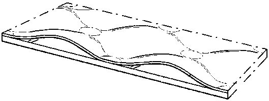
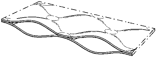
[0026] Such as Figure 4-Figure 5 As shown, at least two pillow-shaped plate heat sinks 4 are provided, and the pillow-shaped plate heat sink 4 adopts the first upper sealing plate 7, the lower second sealing plate 8, and the third sealing plate 9 on the left side. And the fourth sealing plate seal 10 on the right side is set to form a pillow-shaped plate heating radiator, and the pillow-shaped plate heat sink 4 is provided with a weld 11, and the upper or lower ends of the weld 11 are respectively arranged on the pillow-shaped plate heat sink. The upper end and the lower end of the heat sink 4 are arranged at intervals in sequence to form a continuous S-shaped refrigerant flow channel 12, and the refrigerant inlet 5 and the refrigerant outlet 6 are respectively arranged at the welding seam 11 of the pillow-shaped plate heat sink 4 closed end side.

[0027] The indoor pillow-shaped plate heating radiator is mainly composed of pillow-shaped plate heat sinks, upper, lower, left...

Embodiment 2

[0029] Such as Figure 6 As shown, the pillow-shaped plate heating radiator is composed of two metal flat plates 13 and a double-sided pillow-shaped heat sink arranged between the two metal plates 13. Sandwiched in the middle, the pillow-shaped plate heat sinks on both sides can also conduct heat conduction and heat dissipation through the metal plate. This structure not only beautifies the appearance of the heater but also does not affect the heat exchange.

Embodiment 3

[0031] Such as Figure 7 As shown, the pillow-shaped panel heating radiator is a continuously folded screen structure composed of a plurality of unilateral pillow-shaped plate radiators connected end to end. composition.


PUM


Abstract

The invention discloses a pillow-shaped plate type heating radiator which is connected with an outdoor heating unit correspondingly. The heating unit comprises a throttling device, an evaporator and acompressor which are connected in sequence correspondingly. The pillow-shaped plate type heating radiator comprises a pillow-shaped plate type cooling fin. The pillow-shaped plate type cooling fin isformed in the mode that two metal sheets are overlapped and welded together through laser penetration, then the position between the metal sheets expands through a high-pressure fluid, and accordingly, a unilateral pillow-shaped plate type cooling fin or a bilateral pillow-shaped plate type cooling fin with an internal channel and the surface in a wave shape is formed. The pillow-shaped plate type heating radiator is good in heat conductivity, a pillow-shaped wavy structure enhances the heat exchanging performance, through laser melting penetration welding, the loading capacity is high, and the welding performance is stable; compared with a tubular radiator, the accommodating area in a unit space is large; and by adopting the metal sheet type cooling fin, the problem of pipeline freezingis solved, the heating speed is high, quick heating is achieved, system operation is reliable, and the number of the pillow-shaped plate type cooling fin can be increased according to the indoor areasize.

Description

technical field [0001] The invention relates to a pillow-shaped plate heating radiator suitable for heating in the north. Background technique [0002] At present, commercial residences and residential buildings adopt centralized heating methods, especially in northern my country, mainly use pipelines to connect with the hot water source of the hot water company, and the hot water flows into the radiator and heats up through the heat sink. The existing heat dissipation structure either adopts tube heat dissipation or finned plate heat dissipation, and the heat dissipation medium is hot water. The heating pipeline is long, and the heat loss of the pipeline is large during long-distance transportation. To achieve the ideal heating and heat dissipation effect, it is necessary to Installing more heat dissipation components leads to a large footprint of the radiator and increases the installation cost. Contents of the invention [0003] The purpose of the present invention is ...

Claims


Application Information

Patent Timeline
Patent Type & Authority Applications(China)
IPC IPC(8): F28F1/06F28F9/18F24D19/00
CPCF24D19/0002F28F1/06F28F9/18
Inventor 蒋正坤田奎谢家龙
Owner SEHENSTAR ENERGY TECH SUZHOU
Why Eureka
Try Eureka