
a transmission

A transmission and speed change mechanism technology, which is applied to vehicle gearboxes, clutches, transmissions, etc., can solve problems such as cumbersome operation, lower transmission efficiency, and high noise, and achieve simplified shifting steps, simple shifting operations, and improved work efficiency. efficiency effect

Active Publication Date: 2020-03-31
山东迈克拉克工程机械有限公司
View PDF6 Cites 0 Cited by
  • Summary
  • Abstract
  • Description
  • Claims
  • Application Information

AI Technical Summary

Problems solved by technology

[0003] In the process of realizing the present invention, the inventor found that there are at least the following problems in the prior art: the existing stepped transmission needs to be disconnected from the engine to shift gears, and the engine is connected after the gear shift is completed, which is cumbersome and noisy. Large and difficult to shift gears. Once the operation is wrong, it is easy to damage the transmission gears by directly shifting without ignoring the clutch, and this shifting method will increase the idle time of the engine and reduce the transmission efficiency

Method used


Image

  • a transmission
  • a transmission
  • a transmission

Examples


Embodiment Construction

[0023] In order to clearly illustrate the technical features of the present solution, the present invention will be described in detail below through specific implementation methods and in conjunction with the accompanying drawings. The following disclosure provides many different embodiments or examples for implementing different structures of the present invention. To simplify the disclosure of the present invention, components and arrangements of specific examples are described below. Furthermore, the present invention may repeat reference numerals and / or letters in different instances. This repetition is for the purpose of simplicity and clarity and does not in itself indicate a relationship between the various embodiments and / or arrangements discussed. It should be noted that components illustrated in the figures are not necessarily drawn to scale. Descriptions of well-known components and processing techniques and processes are omitted herein to avoid unnecessarily lim...


PUM


Abstract

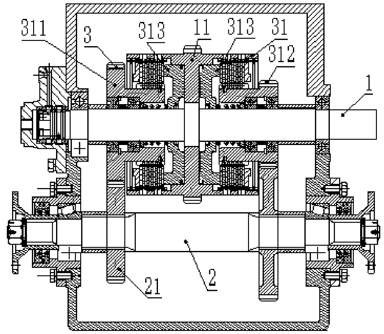
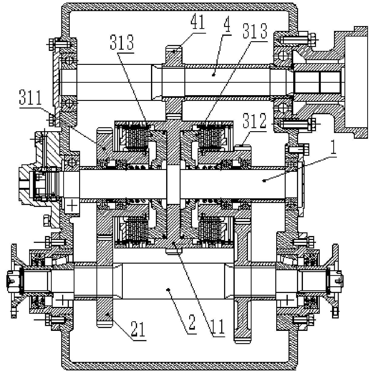
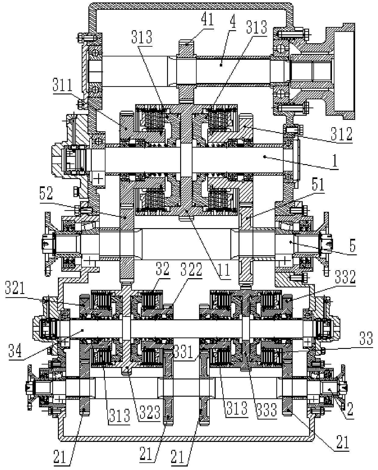
The invention discloses a speed changer which comprises an input shaft and an output shaft. A power gear a is arranged on the input shaft, at least two output gears are arranged on the output shaft, and a speed change mechanism is arranged between the power gear a and the output gear. The speed change mechanism comprises a primary speed change mechanism, the primary speed change mechanism comprises a transmission gear a and a transmission gear b, and the transmission gear a and the transmission gear b are arranged on the two sides of the power gear a correspondingly. The transmission gear a, the transmission gear b and the power gear a are coaxial, clutches are arranged between the transmission gear a and the power gear a and between the transmission gear b and the power gear a, and each of the transmission gear a and the transmission gear b is connected with one output gear. During gear shifting, only different clutches need to be driven to be attached to the power gear a, a power gear b and a power gear c, gear shifting can be directly completed, gear shifting operation is easy, operation is easy, and the situation that wrong operation is carried out, and consequently the speed changer is damaged is avoided. The engine idling time is short, and the work efficiency of an engine is effectively improved.

Description

technical field [0001] The invention relates to the technical field of transmissions, in particular to a stepped transmission capable of direct shifting. Background technique [0002] The transmission is a mechanism used to change the engine speed and torque. It can change the transmission ratio of the output shaft and the input shaft in fixed or stepwise steps, also known as the gearbox. Transmissions are divided into stepped transmissions, continuously variable transmissions, and integrated transmissions. The stepped transmission is the most widely used type at present. It adopts gear transmission and has several fixed-value transmission ratios. Its cost is low and the failure rate is low. And can withstand high torque. [0003] In the process of realizing the present invention, the inventor found that there are at least the following problems in the prior art: the existing stepped transmission needs to be disconnected from the engine to shift gears, and the engine is con...

Claims


Application Information

Patent Timeline
Patent Type & Authority Patents(China)
IPC IPC(8): F16H3/089F16H3/091F16H3/093F16H59/02F16H59/04F16H59/26F16H59/36F16D48/02
CPCF16D48/0206F16D2048/0287F16H3/089F16H3/091F16H3/093F16H59/0204F16H59/04F16H59/26F16H59/36F16H2003/0811F16H2003/0938F16H2059/366F16H2200/0034F16H2200/2035F16H2200/2041F16H2200/2046
Inventor 张新素
Owner 山东迈克拉克工程机械有限公司
Learn More