Novel internal structure of reactor and design method and application of novel internal structure

An internal structure and reactor technology, applied in chemical instruments and methods, treatment with moving solid particles, hydrocarbon oil cracking, etc., can solve the problems of easy wear, uneconomical, limited conversion rate of raw materials, etc.

Pending Publication Date: 2018-03-13
CATECH TECH
View PDF0 Cites 6 Cited by
  • Summary
  • Abstract
  • Description
  • Claims
  • Application Information

AI Technical Summary

Problems solved by technology

But the disadvantages are obvious. The temperature difference between the upper and lower ends of the reactor is large, which is easy to be strained and has a short service life. Since the inlet temperature of the reactor cannot reach the reaction temperature, the actual reaction section is smaller than the length of the reactor; there is no back-mixing of the reaction materials in the reactor, and the There are few contact opportunities between hydrogen and catalyst, and the conversion rate of raw materials is limited. In order to achieve the reaction depth, a large amount of external circulation is required, and the energy consumption of external circulation is high, resulting in high energy consumption of the device and uneconomical; the reaction of light and heavy components in the reactor The time is the same, the gasification rate of light components is high, and the yield of light oil is low

Method used


Image

  • Novel internal structure of reactor and design method and application of novel internal structure
  • Novel internal structure of reactor and design method and application of novel internal structure
  • Novel internal structure of reactor and design method and application of novel internal structure

Examples


Embodiment 1

[0023] This embodiment is applied to the oil-coal slurry bed hydrogenation process.

[0024] 1. Feeding process:

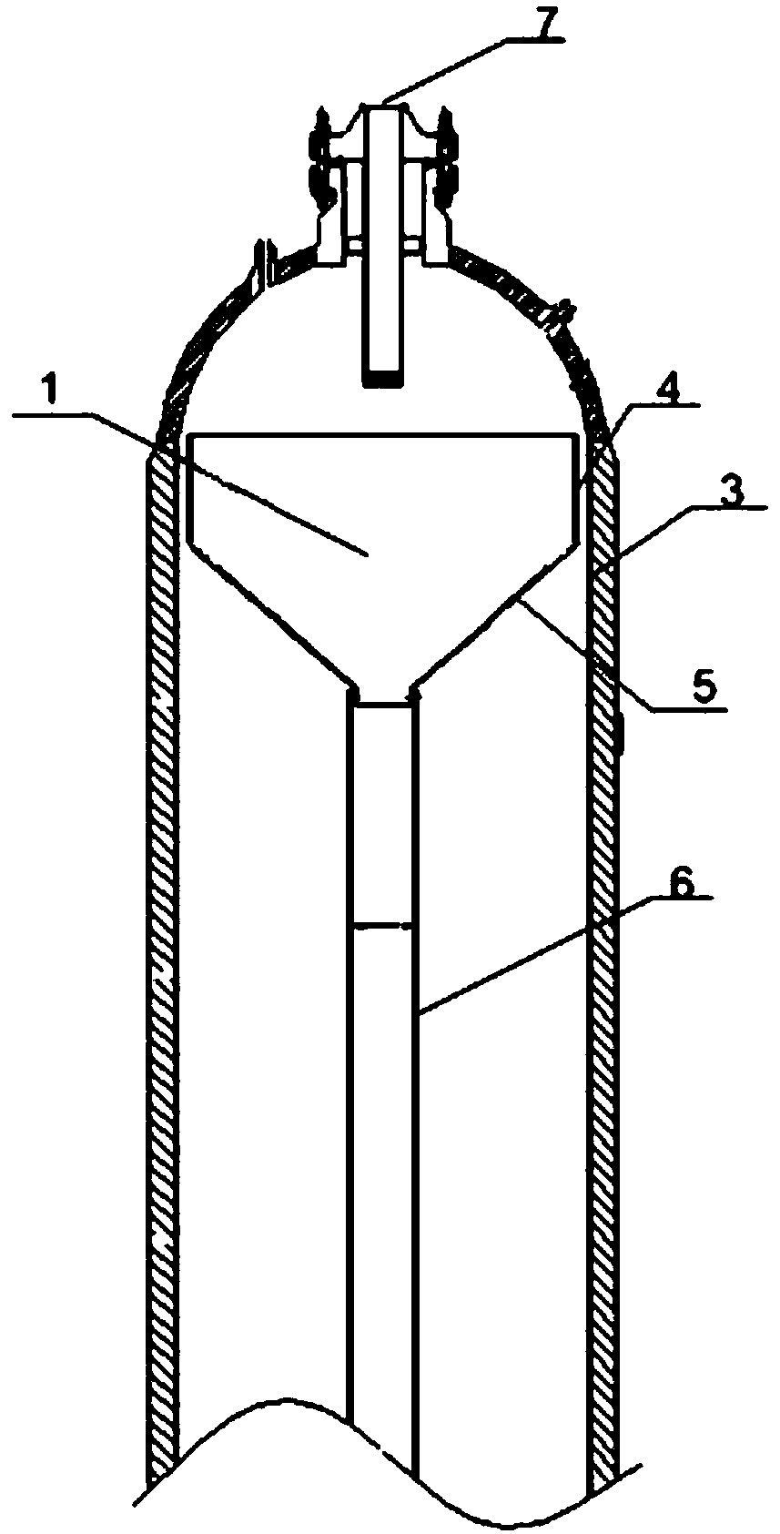
[0025] like figure 1 As shown in the figure, after the oil-coal mixture is pressurized by the circulating pump 9, it is sent to the feed port 8 at the bottom of the reactor barrel and enters the inside of the reactor. The flow is then accelerated along the annular gap between the outer wall 5 of the circular frustum cup and the inner wall 3 of the reactor at the bottom of the circulating blister, and finally passes through the annular gap between the outer wall 4 of the cylindrical cup and the inner wall 3 of the reactor. Continue to rise rapidly to the upper section of the circulating bubble cap 1 and enter the reactor, the space suddenly becomes larger, the speed of the mixture suddenly decreases, the light and heavy components are fully separated, the light components flow out from the discharge port 7 at the top, and the heavy components gravity It falls int...

Embodiment 2

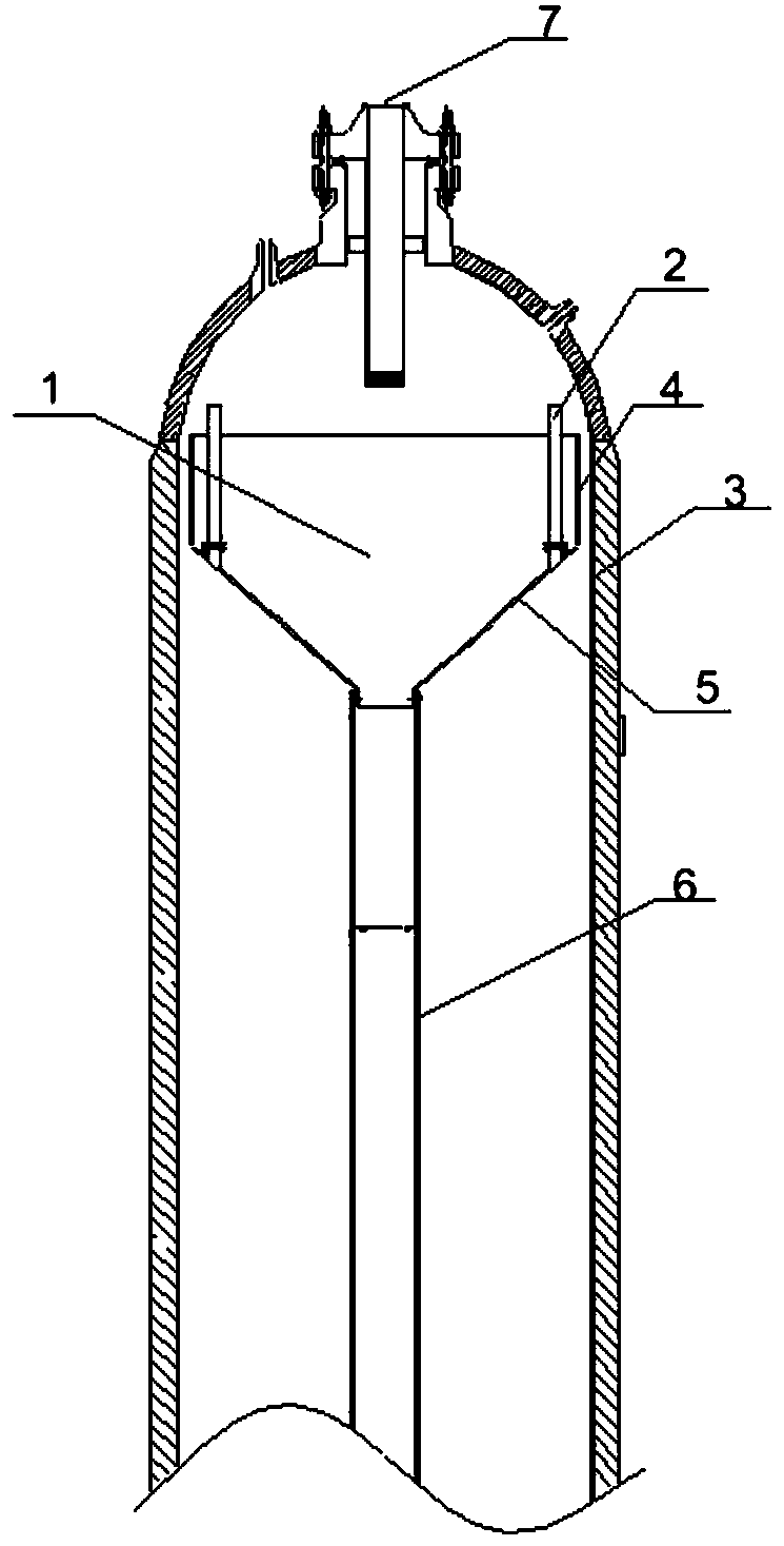
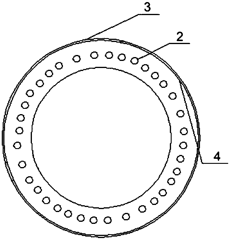
[0032] The overall structure is similar to Embodiment 1, which is applied to heavy oil hydrogenation, and also includes 30 hollow blister risers 2 with opening and closing switches. The upper part is close to the bottom surface of the outer wall 4 of the cylindrical cup cover, and the top opening is slightly higher than the upper periphery of the cylindrical cup cover, such as figure 2 , 3 As shown, the inner diameter of the blister riser 2 is 10 mm.

[0033] The material can also rise rapidly to the top of the circulating blister through the blister riser 2, and its rising speed is close to the annular gap between the outer wall 4 of the cylindrical cup and the inner wall 3 of the reactor, and the number of opening and closing of the blister riser 2 is controlled according to the situation. , so that the rising speed of the material can be better controlled.

[0034] in conclusion:

[0035] It can be seen from the above examples that the hydrogenation reactor of the prese...


PUM


Abstract

The invention relates to a novel internal structure of a reactor and a design method and application of the novel internal structure. The internal structure comprises a reactor barrel, a feeding opening, a discharging opening, a circulating bubble cap, a flow guiding tube and a circulating pump, wherein the feeding opening is positioned in the lower part of the barrel; the discharging opening is positioned in the top of the barrel; the circulating bubble cap comprises a hollow cylindrical cup cap on the upper part, a hollow truncated cone shaped cup cap on the lower part and a plurality of bubble cap rising tubes; the top of the cylindrical cup cap is open and is positioned below the discharging opening; the diameter of the bottom surface of the truncated cone shaped cup cap is smaller than the diameter of the top surface of the truncated cone shaped cup cap; the bottom surface of the truncated cone shaped cup cap is connected with the flow guiding tube; the bubble cap rising tubes areuniformly distributed in the periphery of the circulating bubble cap; the tops of the bubble cap rising tubes are higher than the upper plane of the cylindrical cup cap; the bottoms of the bubble caprising tubes are parallel and level to the truncated cone shaped cup cap; the lower end of the flow guiding tube leads to the bottom of the reactor barrel and communicates with the circulating pump which is positioned on the outside of the reactor barrel; the other end of the circulating pump leads to the feeding opening; and a ring gap between the flow guiding tube and the inner wall of the reactor barrel is far greater than a ring gap between the outer wall of the cylindrical cup cap and the inner wall of the reactor barrel and the inner diameters of the bubble cap rising tubes.

Description

technical field [0001] The invention relates to a novel internal structure of a hydrogenation reactor, belonging to the fields of oil refining chemical industry and coal chemical industry. Background technique [0002] Slurry bed reactor, also known as suspended bed reactor, is a gas-liquid or gas-liquid-solid three-phase reactor. It can process heavy oil with high sulfur, high nitrogen, high heavy metal and high asphaltene content, and can also process oil-coal mixture. In recent years, it has gradually become the key research object of heavy oil processing, direct coal liquefaction and oil-coal co-refining. [0003] At present, the main types of slurry bed reactors are empty cylinder reactors and forced internal circulation reactors. The empty cylinder reactor has a simple structure, and its shape is a slender cylinder, and there are no other redundant components in it except the necessary pipeline inlet and outlet. In order to achieve a sufficient residence time and at...

Claims


Application Information

Patent Timeline
IPC IPC(8): B01J8/22C10G47/26C10G49/12C10G1/06C10G45/16
CPCB01J8/1872B01J8/22C10G1/06C10G45/16C10G47/26C10G49/12
Inventor 李苏安邓清宇王坤朋
Owner CATECH TECH
Why Eureka
Try Eureka