Eureka AIR delivers breakthrough ideas for toughest innovation challenges, trusted by R&D personnel around the world.

Sewage pretreatment device

A sewage pretreatment and equipment technology, applied in water/sewage treatment equipment, water/sewage treatment, biological water/sewage treatment, etc., can solve the problems of incomplete separation of sand and water, complex structure of sand filter, high cost, etc., to achieve clean The effects of long slag interval, small floor space and easy operation and management

Pending Publication Date: 2018-03-09
重庆大学科技企业(集团)有限责任公司
View PDF0 Cites 0 Cited by
  • Summary
  • Abstract
  • Description
  • Claims
  • Application Information

AI Technical Summary

Problems solved by technology

However, in the existing sewage treatment process, after using coarse and fine grids or sand filters, it is necessary to enter another equipment grit chamber for separation of sand and water, and the filtration of coarse and fine grids will easily lead to incomplete separation of sand and water, making the filtration The final sewage with sand residues will block other devices when it enters other devices, and the sand filter has a better filtering effect, but the structure of the sand filter is more complicated, not only with a pressure difference control device, an electric control PLC, but also a hydraulic control valve and other controls. device, the cost is higher

Method used


Image

  • Sewage pretreatment device
  • Sewage pretreatment device
  • Sewage pretreatment device

Examples


Embodiment Construction

[0017] The present invention will be described in further detail below in combination with the accompanying drawings, and specific implementation methods will be given.

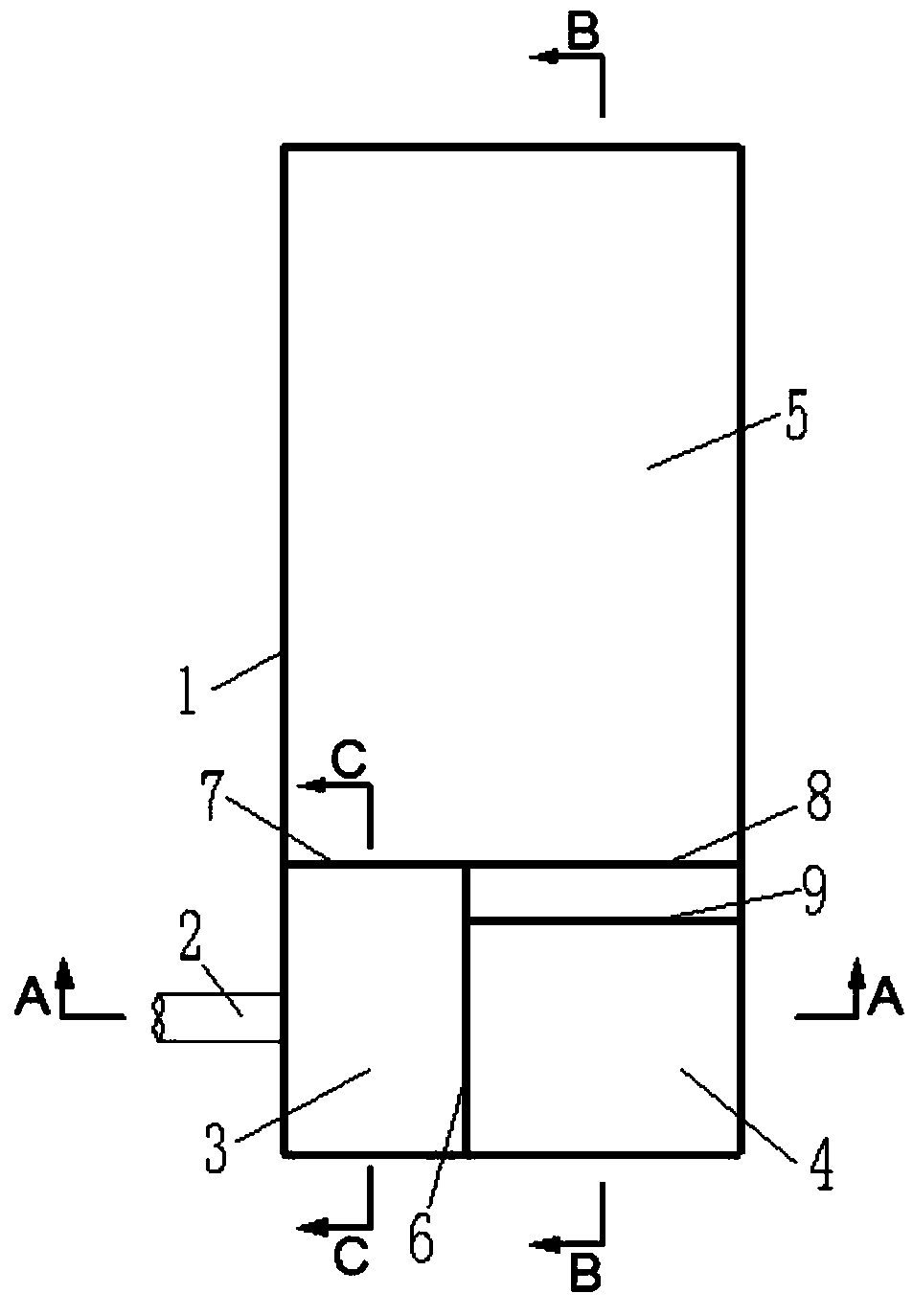
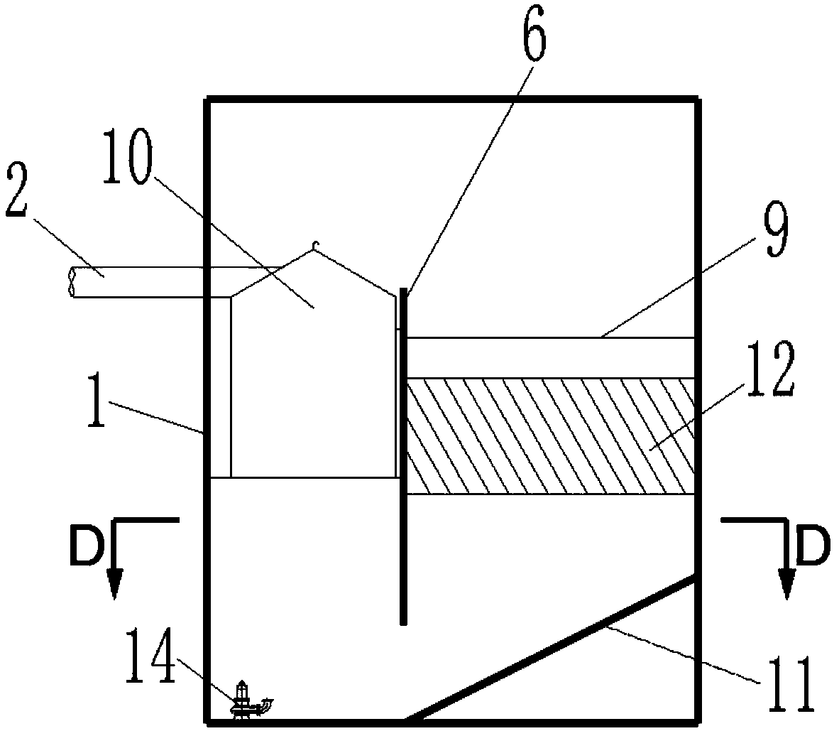
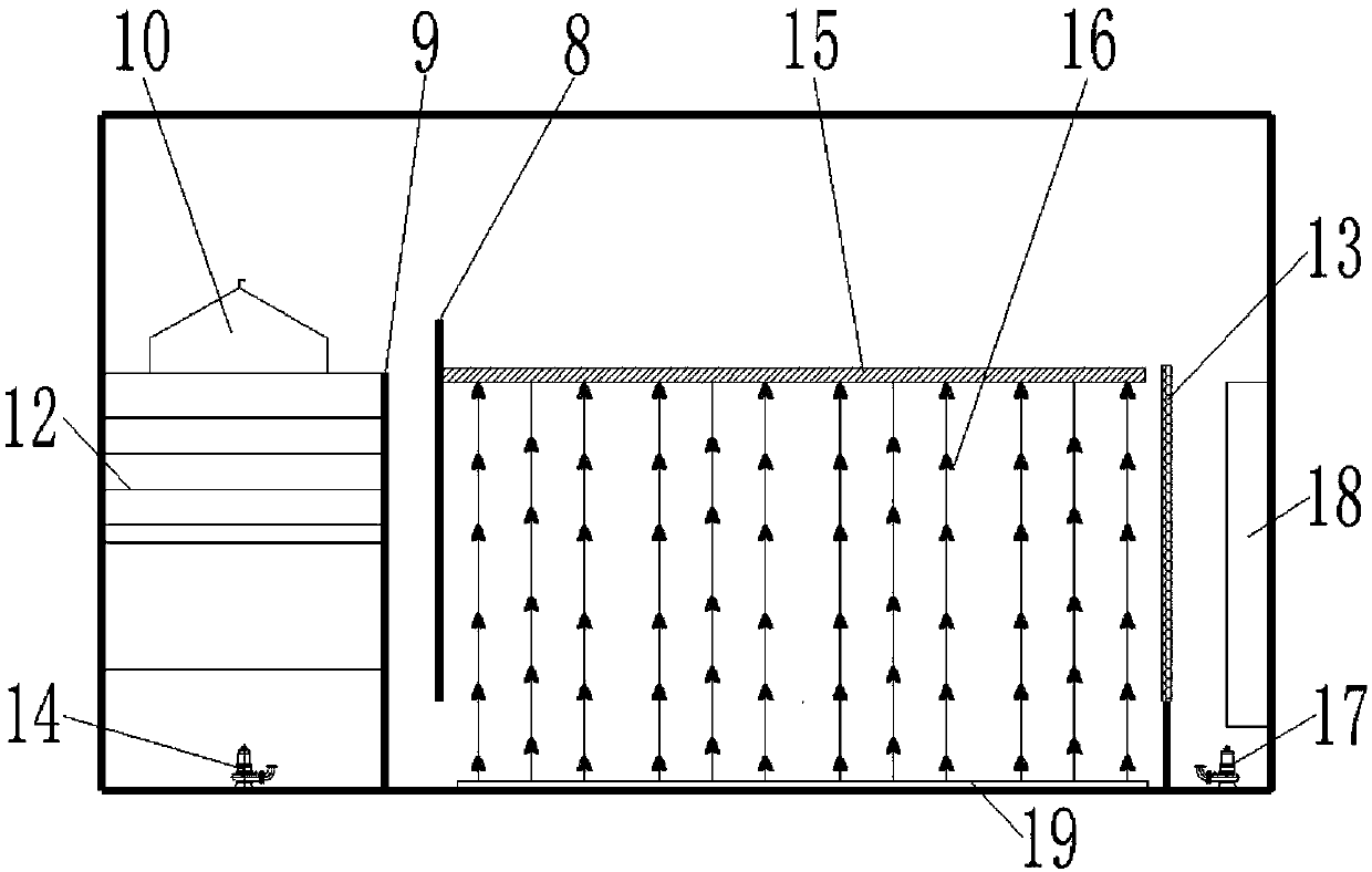
[0018] like Figure 1-5 As shown, a sewage pretreatment device includes a device body 1. The device body 1 is composed of a slag removal chamber 3, a sedimentation phosphorus removal chamber 4 and a hydrolysis adjustment chamber 5. The slag removal chamber 3 is composed of the inner wall of the device body 1, the first baffle 6 and the third baffle 7; the precipitation dephosphorization chamber 4 is surrounded by the inner wall of the equipment body 1, the first baffle 6 and the second baffle 8; the hydrolysis adjustment chamber 5 is surrounded by the inner wall of the equipment body 1, the third baffle 7 Surrounded by the second baffle plate 8; there is a gap between the bottom of the first baffle plate 6 and the bottom of the equipment body 1; there is a gap between the bottom of the second baffle plate 8 a...


PUM


Abstract

A sewage pretreatment device includes a device body composed of a residue removal chamber, and deposition phosphorus removal chamber, and a hydrolysis regulation chamber. A gap is formed between the bottom of a first baffle and the bottom of the device body and another gap is formed between the bottom of a second baffle and the bottom of the device body. A flow guide plate is disposed between thedeposition phosphorus removal chamber and the second baffle. Two sides of the flow guide plate are respectively fixed to a side wall of the device body and a side wall of the first baffle. The bottomof the flow guide plate is fixed to the bottom of the device body. The upper part of the flow guide plate is lower than the upper parts of the first and the second baffles. A residue removal basket isfixedly arranged in the residue removal chamber. A sloping plate zone is arranged in the deposition phosphorus removal chamber and is provided with an electrolysis phosphorus removal apparatus. A plurality layers of flexible expanded packs are arranged in the hydrolysis regulation chamber. Compared with the prior art, the device integrates functions of residue removal, sand removal, phosphorus removal and hydrolysis regulation. The device is high in treatment efficiency, is easy to operate and manage, and is small in occupied area.

Description

technical field [0001] The invention relates to the technical field of sewage treatment, in particular to sewage pretreatment equipment. Background technique [0002] With the continuous development of urbanization in our country, a large amount of sewage has been brought, which not only pollutes water sources for urban residents, but also destroys the surrounding environment of cities and towns. Therefore, the treatment of sewage has become an urgent problem for people to solve. The prevention of sewage The treatment is set according to the water quality requirements of the subsequent treatment process before the sewage enters the traditional sedimentation and biological treatment. The existing sewage treatment process is mainly to filter the sewage through coarse and fine grids, sand filters or screens, and then enter the grit chamber or sand-water separator for separation of sand and water. However, in the existing sewage treatment process, after using coarse and fine gr...

Claims


Application Information

Patent Timeline
IPC IPC(8): C02F9/14C02F101/10C02F101/30
CPCC02F9/00C02F2301/08C02F3/34C02F2101/105C02F2101/30C02F2201/002C02F2201/007C02F1/001C02F1/463
Inventor 何强周健李果张超何高缘王祥勇孙通
Owner 重庆大学科技企业(集团)有限责任公司
Why Eureka
Eureka Blog
Learn More