
Numerically-controlled machine tool

A CNC lathe and bed technology, applied in the field of CNC machine tools, can solve the problems of inaccurate positioning of workpieces and low machining accuracy, and achieve the effects of easy placement, less damage, and improved machining accuracy

Inactive Publication Date: 2018-03-09
秦科
View PDF4 Cites 0 Cited by
  • Summary
  • Abstract
  • Description
  • Claims
  • Application Information

AI Technical Summary

Problems solved by technology

[0003] The purpose of the present invention is to provide a numerically controlled machine tool. The technical problem to be solved is: the lathes on the market do not accurately position the workpiece, resulting in low machining accuracy.

Method used


Image

  • Numerically-controlled machine tool

Examples


Embodiment Construction

[0010] The principles and features of the present invention will be described below with reference to the accompanying drawings. The examples cited are only used to explain the present invention, and are not used to limit the scope of the present invention.

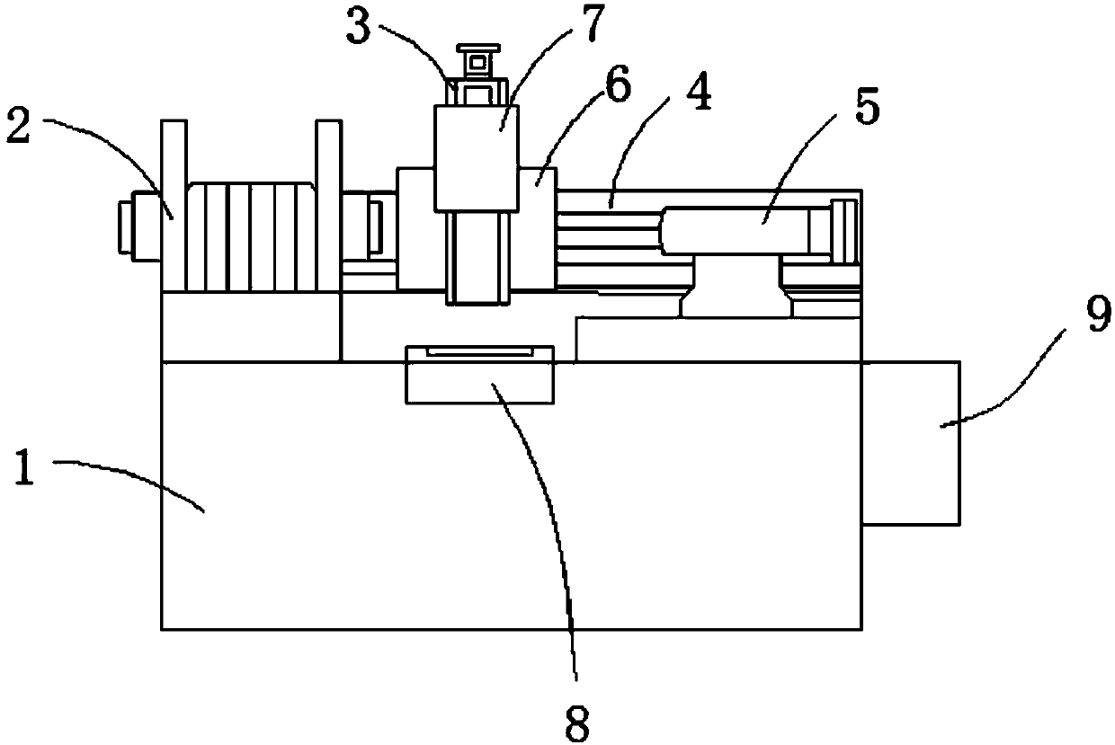
[0011] Such as figure 1 As shown, a precision CNC lathe includes a bed 1, a headstock 2, a Z-axis guideway 3, an X-axis guideway 4, and a tailstock 5. The headstock 2 and the X-axis guideway 4 are both fixed on the bed At the upper end of 1, the X-axis guide 4 is located on one side of the headstock 2, the X-axis guide 4 is equipped with a laterally movable X-axis feed table 6, and the Z-axis guide 3 is fixed on the On the X-axis feed table 6, the Z-axis guide 3 is equipped with a vertically movable Z-axis feed table 7, and the guide grooves of the X-axis guide 4 and the Z-axis guide 3 are made of graphene , The tailstock 5 is placed on the side of the X-axis guide rail 4 away from the headstock 2; the bed 1 is provided wit...


PUM


Abstract

The invention relates to a numerically-controlled machine tool. The numerically-controlled machine tool comprises a machine tool body, a spindle box, a Z-axis guide rail, an X-axis guide rail and a tailstock. The spindle box and the X-axis guide rail are both fixedly arranged at the upper end of the machine tool body, the X-axis guide rail is positioned on one side of the spindle box, an X-axis feeding table capable of moving transversely is mounted on the X-axis guide rail, the Z-axis guide rail is fixedly arranged on the X-axis feeding table, an Z-axis feeding table capable of moving vertically is mounted on the Z-axis guide rail, guide grooves of the X-axis guide rail and the Z-axis guide rail are both made from graphene, and the tailstock is arranged on one side, away from the spindlebox, of the X-axis guide rail. The machine tool body is provided with a tank corresponding to the lower portion of the Z-axis feeding table, an electromagnetic device is detachably arranged in the tank, the upper portion of the electromagnetic device extends out of the tank, and the upper end face of the electromagnetic device structurally matched with the a workpiece. Compared with the prior art,the numerically-controlled machine tool has advantages of high accuracy in workpiece positioning and machining accuracy improvement.

Description

Technical field [0001] The invention relates to the field of numerical control processing, in particular to a numerical control machine tool. Background technique [0002] The guide rail of the CNC lathe has a very important position in the entire lathe, and it largely determines the rigidity, precision and accuracy of the lathe. The main task of the guide rail is to load the supporting parts; to guide the execution parts. The current lathes on the market are not precise in positioning the workpiece, resulting in low machining accuracy. Summary of the invention [0003] The purpose of the present invention is to provide a numerically controlled machine tool. The technical problem to be solved is that the current lathes on the market have inaccurate positioning of the processed parts, resulting in low processing accuracy. [0004] The technical solution of the present invention to solve the above technical problems is as follows: A precise numerical control lathe includes a bed, a ...

Claims


Application Information

Patent Timeline
IPC IPC(8): B23Q1/01B23Q3/154
CPCB23Q1/017B23Q3/1543
Inventor 秦科
Owner 秦科
Learn More