
Steel fiber drawing device in concrete

A technology of drawing device and steel fiber, which is applied in the direction of measuring device, adopting mechanical device, instrument, etc., can solve the problems of affecting test results, unstable clamping force, unreliable clamping, etc., and achieves convenient drawing operation, The clamping is firm and reliable, and the effect of increasing the maximum value

Active Publication Date: 2018-03-06
JILIN JIANZHU UNIVERSITY
View PDF11 Cites 9 Cited by
  • Summary
  • Abstract
  • Description
  • Claims
  • Application Information

AI Technical Summary

Problems solved by technology

The traditional test device adopts manual screw clamping or winding steel wire to clamp and fix the steel fiber. For the steel fiber with high strength and high hardness, it is easy to be unreliable clamping, easy to be pinched and unable to be clamped during the drawing process. Winding and other problems; use bench vise to clamp and fix the test piece, the clamping force of the bench vise will affect the test results and the clamping force is unstable during the test process, which is not conducive to the test

Method used


Image

  • Steel fiber drawing device in concrete
  • Steel fiber drawing device in concrete
  • Steel fiber drawing device in concrete

Examples


Embodiment Construction

[0023] The following will clearly and completely describe the technical solutions in the embodiments of the present invention with reference to the accompanying drawings in the embodiments of the present invention. Obviously, the described embodiments are only some, not all, embodiments of the present invention.

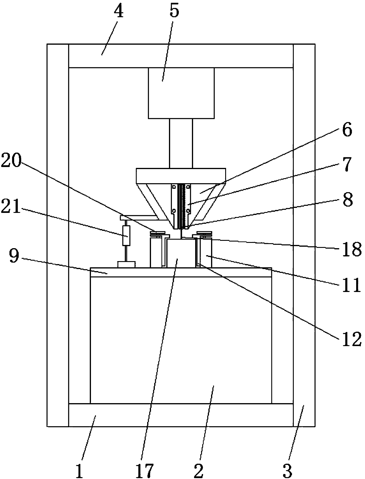
[0024] refer to Figure 1-8 , a steel fiber drawing device in concrete, comprising a base 1, a cabinet 2, a frame, a test piece fixing device and a pulling device, the cabinet 2 is located on the top of the base 1, and the test piece fixing device is located on the top of the cabinet 2, The drawing device is located directly above the specimen fixing device, and is characterized in that the frame is composed of a vertical support 3 fixedly connected to both sides of the base 1 and a crossbeam 4 fixedly connected between the top of the vertical support 3, the crossbeam 4 A hydraulic tension device 5 is installed on the bottom surface of the hydraulic tension device 5,...


PUM


Abstract

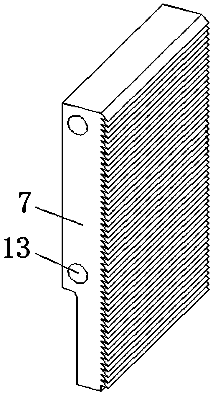
The invention discloses a steel fiber drawing device in concrete. The device comprises a pedestal, an engine case, a rack, a test-piece fixing device and a drawing device, wherein the rack consists ofa vertical support and a cross beam, the undersurface of the cross beam is provided with a hydraulic pulling device, a clamp fixing device is connected on the output end of the bottom of the hydraulic pulling device, the drawing device comprises two clamping plates, the inner side surfaces of the clamping plates are respectively connected with aluminum plates, the test-piece fixing device comprises a fixed pedestal, a horizontal spacing vertical plate, a horizontal baffle plate and a vertical lifting standing plate, a test-piece is arranged on the fixed pedestal, and the upper part of steel fiber in the test-piece is clamped between the aluminum plates. According to the steel fiber drawing device, the aluminum plates with arc-shaped tooth opening structures are adopted, so that clamping is firm and reliable, the accuracy of drawing steel wire test force is increased, and the maximum value of drawing steel wire test force is promoted; clamping sizes of the test-piece fixing device canall be adjusted, the drawing operation is convenient, the data accuracy rate is high, and the efficiency of drawing tests is improved.

Description

technical field [0001] The invention relates to the technical field of test equipment, in particular to a steel fiber drawing device in concrete. Background technique [0002] In the process of building construction, the concrete reinforcement needs to test the bonding ability of the interface between the steel fiber and the concrete on the test piece, so as to test the quality of the concrete reinforcement structure and ensure the quality of the construction project. The traditional test device adopts manual screw clamping or winding steel wire to clamp and fix the steel fiber. For the steel fiber with high strength and high hardness, it is easy to be unreliable clamping, easy to be pinched and unable to be clamped during the drawing process. Winding and other problems; use bench vise to clamp and fix the test piece, the clamping force of the bench vise has an impact on the test results and the clamping force is unstable during the test process, which is not conducive to th...

Claims


Application Information

Patent Timeline
Patent Type & Authority Applications(China)
IPC IPC(8): G01N19/04
CPCG01N19/04
Inventor 李妍董文洋郭丹峰王勃王淼
Owner JILIN JIANZHU UNIVERSITY
Learn More