
Mixed gas ignition diffusing device

A technology of mixing gas and gas, applied to gas fuel burners, combustion methods, combustion types, etc., can solve the problems of complex tower structure, high ignition failure rate, and large operating noise, so as to reduce the number of configurations and simplify the tower Structural, balanced effects of pressure fluctuations

Pending Publication Date: 2018-03-06
JIANGHAN UNIVERSITY
View PDF0 Cites 0 Cited by
  • Summary
  • Abstract
  • Description
  • Claims
  • Application Information

AI Technical Summary

Problems solved by technology

[0003] If two or more types of gas are involved in the ignition and combustion, and there is a large difference in the diffusion flow rate of different types of gas or generally low, but still follow the traditional design habits, it will often result in poor stability of the diffusion tower , gas ignition and release combustion effect is not ideal, prone to backfire or fire accidents, etc.
[0004] The traditional multi-gas ignition and diffusion process has disadvantages such as high ignition failure rate, high investment cost, complex tower structure and poor stability, short service life of the torch head, and high operating noise, which seriously affects the normal production of the enterprise and the health of the surrounding people. Personal safety has become a serious obstacle to the development of metallurgical enterprises

Method used


Image

  • Mixed gas ignition diffusing device
  • Mixed gas ignition diffusing device

Examples


Embodiment Construction

[0026] The patent will be further described below in conjunction with the accompanying drawings and specific embodiments, so that those skilled in the art can better understand the patent and implement it, but the examples given are not intended to limit the patent.

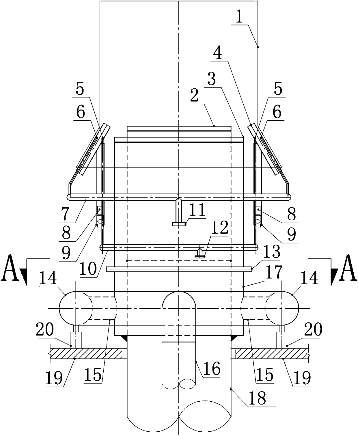
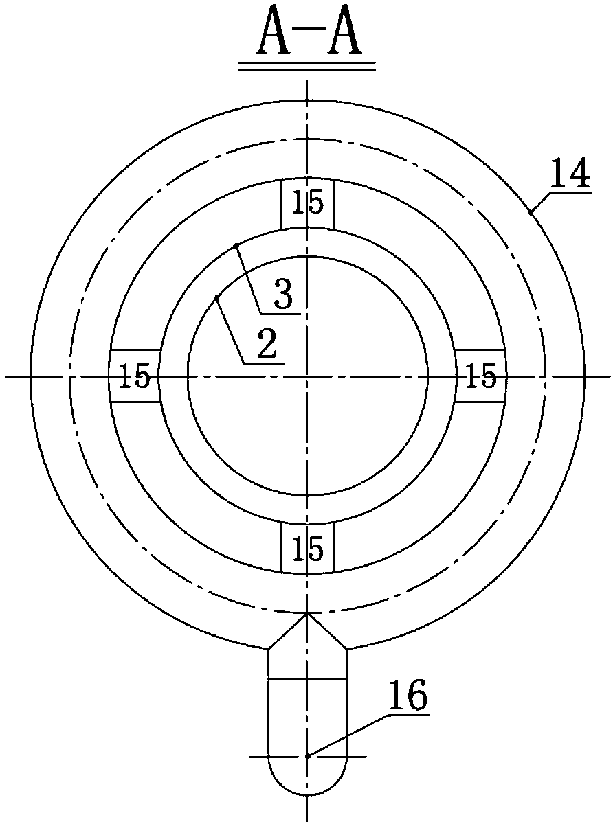
[0027] like figure 1 , figure 2 As shown, a mixed gas ignition and dispersing device includes an ignition gas ring pipe 7, an ignition gas ring pipe 10, an ignition burner 4, an outer swirl gas ring pipe 14, a high-altitude igniter 9, an outer swirl sheet 3, an inner swirl The flow sheet 2, the windproof outer cover 1, the bottom sleeve 17 of the torch head, the flange 13 connecting the outer swirl sheet 3, etc. The inner swirl sheet 2 is ignited and diffused as gas ①, and the gas ignited and diffused between the outer wall of the inner swirl sheet 2 and the inner wall of the outer swirl sheet 3 is outer swirl gas ②.

[0028] Inner swirl gas connecting pipe 18 connects from mixed gas release tower tower frame ...


PUM


Abstract

The invention discloses a mixed gas ignition diffusing device. The mixed gas ignition diffusing device comprises an outer spinning disk, an inner spinning disk, high-altitude igniters and fire-leadingburners; the inner spinning disk is arranged at the top end of an inner spinning gas connection pipe, gas (1) needing to be diffused is introduced into the inner spinning disk through the inner spinning gas connection pipe, the outer spinning disk is arranged on the periphery of the inner spinning disk in a sleeving mode and fixed to the outer wall of the inner spinning gas connection pipe through a torch head bottom sleeve, and gas (2) needing to be diffused is introduced into the position between the outer wall of the inner spinning disk and the inner wall of the outer spinning disk throughthe torch head bottom sleeve; the fire-leading burners are arranged on the periphery of the top of the outer spinning disk, fire-leading nozzles and ignition nozzles are arranged in the fire-leadingburners, ignition gas is introduced into the ignition nozzles through ignition gas branch pipes, and ignition gas is introduced into the fire-leading nozzles through fire-leading gas branch pipes; andthe high-altitude igniters are used for igniting the ignition nozzles. The mixed gas ignition diffusing device can meet the diffusing requirements of different kinds of gas and has the advantages ofbeing low in investment cost, long in service life, low in operation noise, safe, reliable and the like.

Description

technical field [0001] This patent belongs to the field of gas ignition and diffusion equipment, and relates to an ignition and diffusion equipment, in particular to a mixed gas ignition and diffusion device. Background technique [0002] At present, in the gas ignition and diffusion process of metallurgical enterprises, different types of gas need to be ignited and diffused through their own torch heads. Considering safety factors, the torch heads for gas ignition and diffusion are generally set on towers with a height of 40-50m. [0003] If two or more types of gas are involved in the ignition and combustion, and there is a large difference in the diffusion flow rate of different types of gas or generally low, but still follow the traditional design habits, it will often result in poor stability of the diffusion tower , The effect of gas ignition and diffusion is not ideal, and tempering or fire-off accidents are prone to occur. [0004] The traditional multi-gas ignition...

Claims


Application Information

Patent Timeline
IPC IPC(8): F23D14/02F23D14/46F23D14/72
CPCF23D14/02F23D14/46F23D14/72
Inventor 柳昀熠鲁建雄
Owner JIANGHAN UNIVERSITY
Learn More