Comprehensive pipe rack and application method thereof

A technology of integrated pipe gallery and pipe gallery, which is applied in the sewer pipeline system, water conservancy project, waterway system, etc., can solve the problems that municipal pipelines cannot be unified into the gallery, increase the cost of sewage purification treatment, and the purification treatment is much more complicated. The effect of easy management and operation and maintenance, simple structure and less technical requirements

Inactive Publication Date: 2018-03-06
XI AN JIAOTONG UNIV
View PDF8 Cites 2 Cited by
  • Summary
  • Abstract
  • Description
  • Claims
  • Application Information

AI Technical Summary

Problems solved by technology

The first layout method above is the traditional open cut and straight row method. This method needs to excavate the road surface, resulting in a "zipper of the road" in the city. At the same time, it cannot achieve a unified entrance of municipal pipelines. This method should be eliminated
Although the second method mentioned above can be understood as rainwater and domestic sewage sharing a pipeline, it also meets the requirements of the pipeline entering the corridor. However, since the domestic sewage purification process is much more complicated than the rainwater purification treatment, domestic sewage purification needs Large-scale equipment and instruments, and rainwater can be used for farmland irrigation and other purposes with simple or even no treatment
If the rainwater is directly discharged into the domestic sewage pipeline, the amount of domestic sewage that needs to be treated will be greatly increased, and the cost of sewage purification will be increased.

Method used


Image

  • Comprehensive pipe rack and application method thereof
  • Comprehensive pipe rack and application method thereof
  • Comprehensive pipe rack and application method thereof

Examples


Embodiment Construction

[0028] The present invention will be further described in detail below in conjunction with specific embodiments, which are explanations of the present invention rather than limitations.

[0029] In order to describe the present invention clearly, all the descriptions about the number of integrated pipe gallery cabins in its description are different from the commonly used ones. The number of cabins of the integrated pipe gallery in the present invention refers to the number of cabins of the integrated pipe gallery body, rather than the sum of the number of the main body and the auxiliary water collection tanks and drainage cabins in the entire integrated pipe gallery.

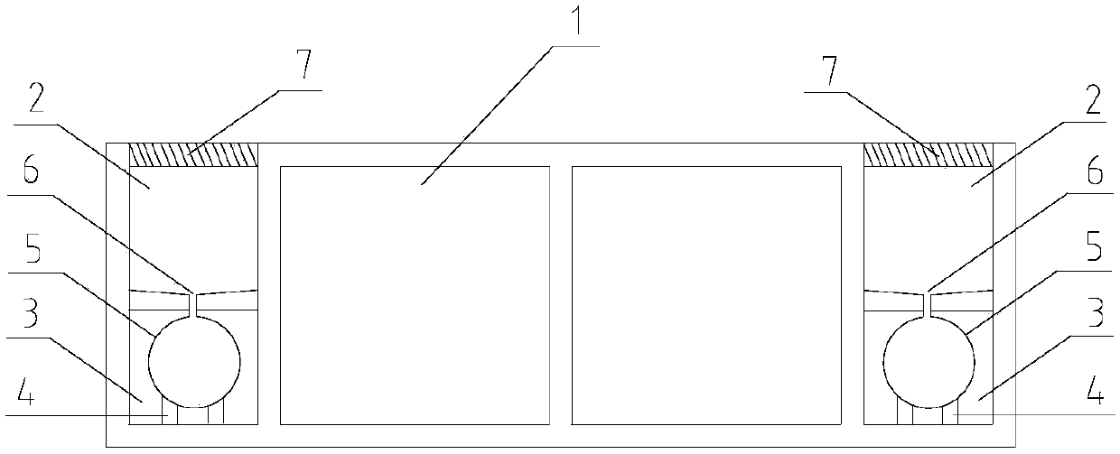
[0030] A comprehensive pipe gallery according to the present invention includes a pipe gallery body 1 and an auxiliary cabin arranged on one or both sides. The drain cover 7 is provided with a number of drain holes, and the bottom surface of the water collection tank 2 is concavely arranged and passes through t...


PUM


Abstract

The invention discloses a comprehensive pipe rack and an application method thereof. The comprehensive pipe rack comprises a pipe rack body, and auxiliary cabins arranged on one side or two sides; theauxiliary cabins comprise water collecting cabins and water drainage cabins arranged in sequence from top to bottom; water drainage pipes are erected in the water drainage cabins; water drainage cover plates are arranged above the water collecting cabins; and connecting pipes communicating with the water drainage pipes are longitudinally arranged on the bottom surfaces at intervals. The comprehensive pipe rack is constructed at the lower part of a pavement; when the precipitation of the pavement is low, accumulated water is gathered into the water collecting cabins through the water drainagecover plates, and then, flows into the water drainage pipes through the connecting pipes; when the precipitation of the pavement is higher, the accumulated water is gathered into the water collectingcabins through the water drainage cover plates, and then, flows into the water drainage pipes through the connecting pipes; and when the water drainage pipes are located in a full-load state, rainwater is directly collected in the water collecting cabins. The water collecting cabins and the water drainage cabins are arranged at the side parts of the comprehensive pipe rack body for achieving the rainwater collection, drainage and short-time storage functions.

Description

technical field [0001] The invention relates to the technical field of municipal infrastructure construction, in particular to a comprehensive pipe gallery and its use method. Background technique [0002] The comprehensive pipe gallery is two or more box culvert tunnels built underground in the city to accommodate urban pipelines such as water supply, drainage, natural gas, electricity, and communications. The unified planning and management of the municipal pipe network can be realized through the construction of the comprehensive pipe gallery. [0003] The Ministry of Housing and Urban-Rural Development's "Notice on Improving Urban Drainage and Waterlogging Prevention Capability and Promoting the Construction of Urban Underground Comprehensive Pipe Gallery" pointed out that urban drainage and waterlogging prevention should be promoted in coordination with urban underground comprehensive pipe gallery and sponge city construction. The role of waterlogging, stagnation, stor...

Claims


Application Information

Patent Timeline
IPC IPC(8): E02D29/045E03F3/02
CPCE02D29/045E03F3/02
Inventor 马鸿敏马建勋
Owner XI AN JIAOTONG UNIV
Why Eureka
Try Eureka