A method for sealing the leakage point between the branch port of the natural gas trunk pipeline and the root valve of the branch pipeline from the inside
What is Al technical title?
Al technical title is built by PatSnap Al team. It summarizes the technical point description of the patent document.
A leak point, natural gas technology, applied in the direction of pipes/pipe joints/pipe fittings, pipe components, mechanical equipment, etc., can solve the problems of inapplicable trunk pipelines and branch pipelines, affecting the normal transportation of natural gas, waste of resources and the environment, etc. The effect of convenience, less environmental damage and high safety factor
Active Publication Date: 2019-05-24
CHINA PETROLEUM & CHEM CORP +1
View PDF6 Cites 0 Cited by
Summary
Abstract
Description
Claims
Application Information
AI Technical Summary
This helps you quickly interpret patents by identifying the three key elements:
Problems solved by technology
Method used
Benefits of technology
Problems solved by technology
The above treatment method can be used to deal with pipeline leakage between the two valves on the branch pipeline, but it is not suitable for the treatment of the leakage point between the main pipeline and the root valve of the branch pipeline, because there is no other valve between the root valve of the branch pipeline and the main pipeline In order to deal with the leakage between the branch of the trunk pipeline and the root valve of the branch pipeline, it is necessary to close the valves located upstream and downstream of the branch of the trunk pipeline, which will cause the suspension of the entire trunk pipeline and seriously affect the normal transportation of natural gas. Venting the main pipeline between the two valves will also cause a lot of waste of resources and environmental pollution
Method used
Image
Click on the blue label to locate the original text in one second.
Reading with bidirectional positioning of images and text.
Examples
Embodiment Construction
[0019] The principles and features of the present invention will be further described in detail below with reference to the accompanying drawings and specific embodiments. The examples cited are only used to explain the present invention, not to limit the scope of the present invention.
[0020] The equipment used in the method provided by the present invention (such as grease injection and drainage devices) are all conventional equipment, and the materials and drugs used (such as leak-stopping cement, fiber impregnated glue or fiber cloth) are all commercially available products.
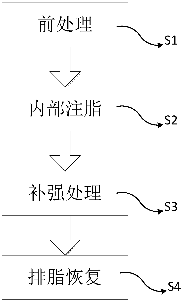
[0021] Such as figure 1 As shown, the present invention provides a method for blocking the leakage point between the branch of a natural gas trunk pipeline and the root valve of the branch pipeline from the inside, which includes the following steps:
[0022] S1. Pre-treatment: Close the root valve on the branch pipeline and the nearest shut-off valve downstream, and vent the pipe between the root valve a...
PUM
Abstract
The invention relates to a method for blocking the leakage points between natural gas main pipeline branch openings and a branch line pipeline root valve from the inside. The method comprises following steps that S1, pretreatment, wherein a branch line pipeline upper root valve and a downstream stop valve closest to the branch line pipeline upper root valve are closed, a pipeline between the two valves is emptied, and the emptied pipeline is dismounted from the root valve; S2, internal grease injecting, wherein a grease injecting and discharging device is arranged on an outlet of the root valve, seal grease is injected, and the leakage points are temporarily blocked; S3, reinforcing treatment, the leakage points are cleaned and ground from the outer portion of the pipeline, leakage stop cement gum is smeared and aligned, and after the leakage stop cement gum is completely hardened, a fiber cloth is used for winding the leakage point pipeline, and bonding is carried out through epoxy impregnating resin; S4, grease discharging recovery, wherein after seal grease is discharged, the root valve is closed, the grease injecting and discharging device is dismantled, an original pipeline isreassembled, and leakage stoop is finished. The method has the beneficial effects that a main pipeline is subject to conveying belt pressure leakage stop continuously, the method is simple, a large amount of emptying is not needed, the leakage stop cost is low, the damage to the environment is small, and the leakage stop effect is good.
Description
Technical field [0001] The invention belongs to the field of natural gas long-distance pipeline leakage treatment, and in particular relates to a method for internally blocking the leakage point between the branch of a weather trunk pipeline and the root valve of the branch pipeline. Background technique [0002] Long-distance oil and gas pipelines include buried main pipelines and surface pipeline ancillary equipment. Surface pipeline ancillary equipment includes oil and gas sub-transmission stations and line cutoff valve chambers. Stations and valve chambers have bypass pipelines, valves and pressure gauges. There are various types and connection methods of ancillary equipment. Due to improper installation methods or product quality defects, oil and gas leaks are likely to occur under the condition of medium pressure fluctuations. Because the pipeline transports high-pressure oil and gas, which is a flammable and explosive medium, once it leaks, it is likely to cause major safe...
Claims
Application Information
Patent Timeline
Application Date:The date an application was filed.
Publication Date:The date a patent or application was officially published.
First Publication Date:The earliest publication date of a patent with the same application number.
Issue Date:Publication date of the patent grant document.
PCT Entry Date:The Entry date of PCT National Phase.
Estimated Expiry Date:The statutory expiry date of a patent right according to the Patent Law, and it is the longest term of protection that the patent right can achieve without the termination of the patent right due to other reasons(Term extension factor has been taken into account ).
Invalid Date:Actual expiry date is based on effective date or publication date of legal transaction data of invalid patent.