
Profile cutting device

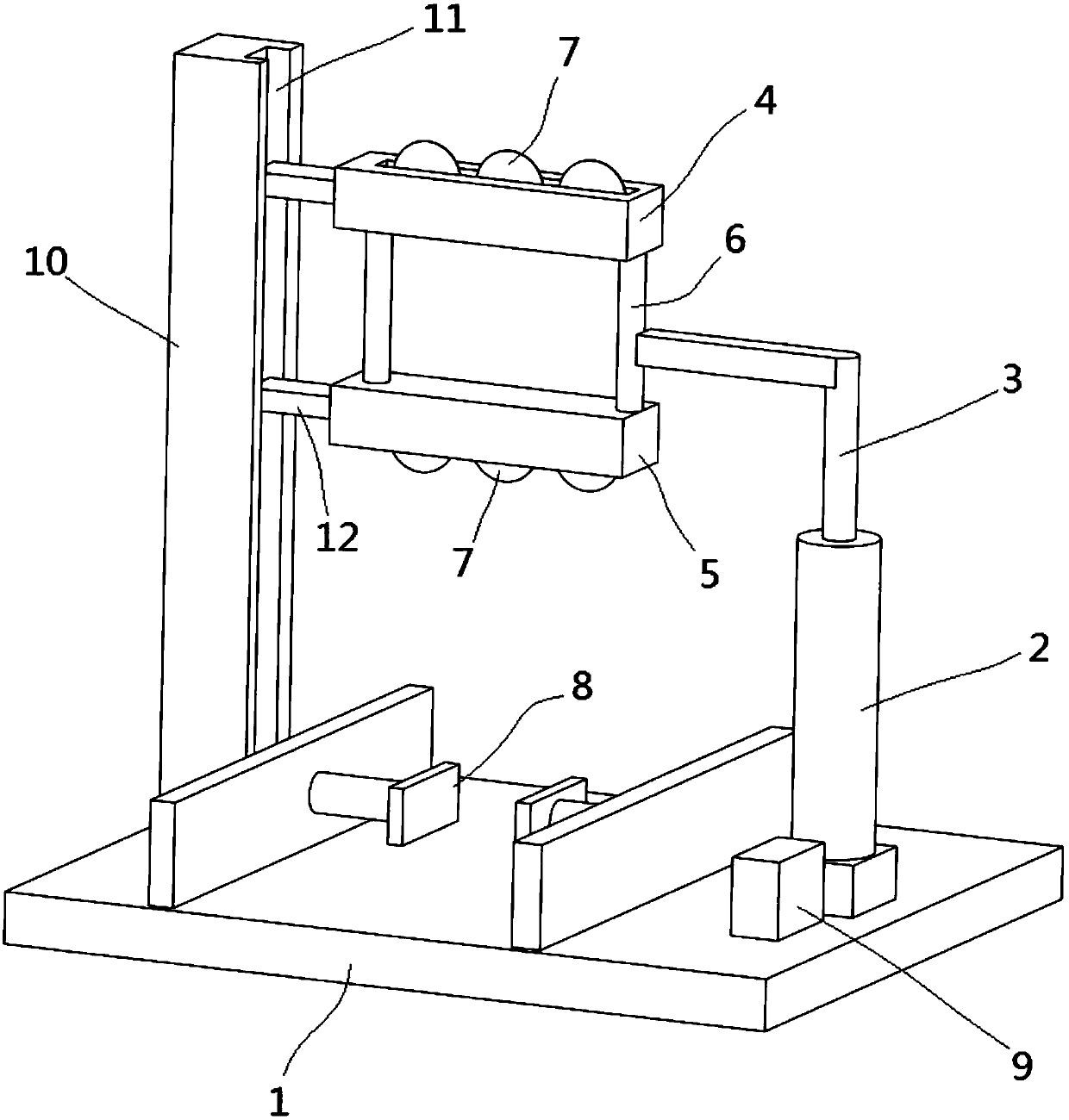
A cutting device and profile technology, applied in metal processing and other directions, can solve problems such as difficult polishing and grinding, lack of support, construction quality or mechanical structural influence, etc., to achieve the effect of easy polishing and power saving

Inactive Publication Date: 2018-02-23
扬州丽合华工程建设有限公司
View PDF0 Cites 3 Cited by
  • Summary
  • Abstract
  • Description
  • Claims
  • Application Information

AI Technical Summary

Problems solved by technology

[0003] In actual use, the profile needs secondary processing such as cutting. Due to the special structure of the profile, there is an empty groove on the profile, so that there is no support device inside the profile at some positions, and no internal support can be obtained. When cutting, because the diameter of the existing cutting blade is too large, the contact area between the blade and the profile is small, and the stress is too concentrated, which will cause the profile to be deformed to varying degrees. The profiles in the prior art are all cut from the outside to the inside. The area with the largest deformation is located inside the profile, which is difficult to polish and grind, which reduces the mechanical properties of the profile and adversely affects the quality of the building or the mechanical structure

Method used


Image

  • Profile cutting device
  • Profile cutting device

Examples


Embodiment Construction

[0018] Embodiments of the technical solutions of the present invention will be described in detail below in conjunction with the accompanying drawings. The following examples are only used to illustrate the technical solutions of the present invention more clearly, and therefore are only examples, rather than limiting the protection scope of the present invention.

[0019] It should be noted that, unless otherwise specified, the technical terms or scientific terms used in this application shall have the usual meanings understood by those skilled in the art to which the present invention belongs.

[0020] In the description of the present application, it should be understood that the terms "center", "longitudinal", "transverse", "length", "width", "thickness", "upper", "lower", "front", " Back", "Left", "Right", "Vertical", "Horizontal", "Top", "Bottom", "Inner", "Outer", "Clockwise", "Counterclockwise", "Axial", The orientation or positional relationship indicated by "radial"...


PUM


Abstract

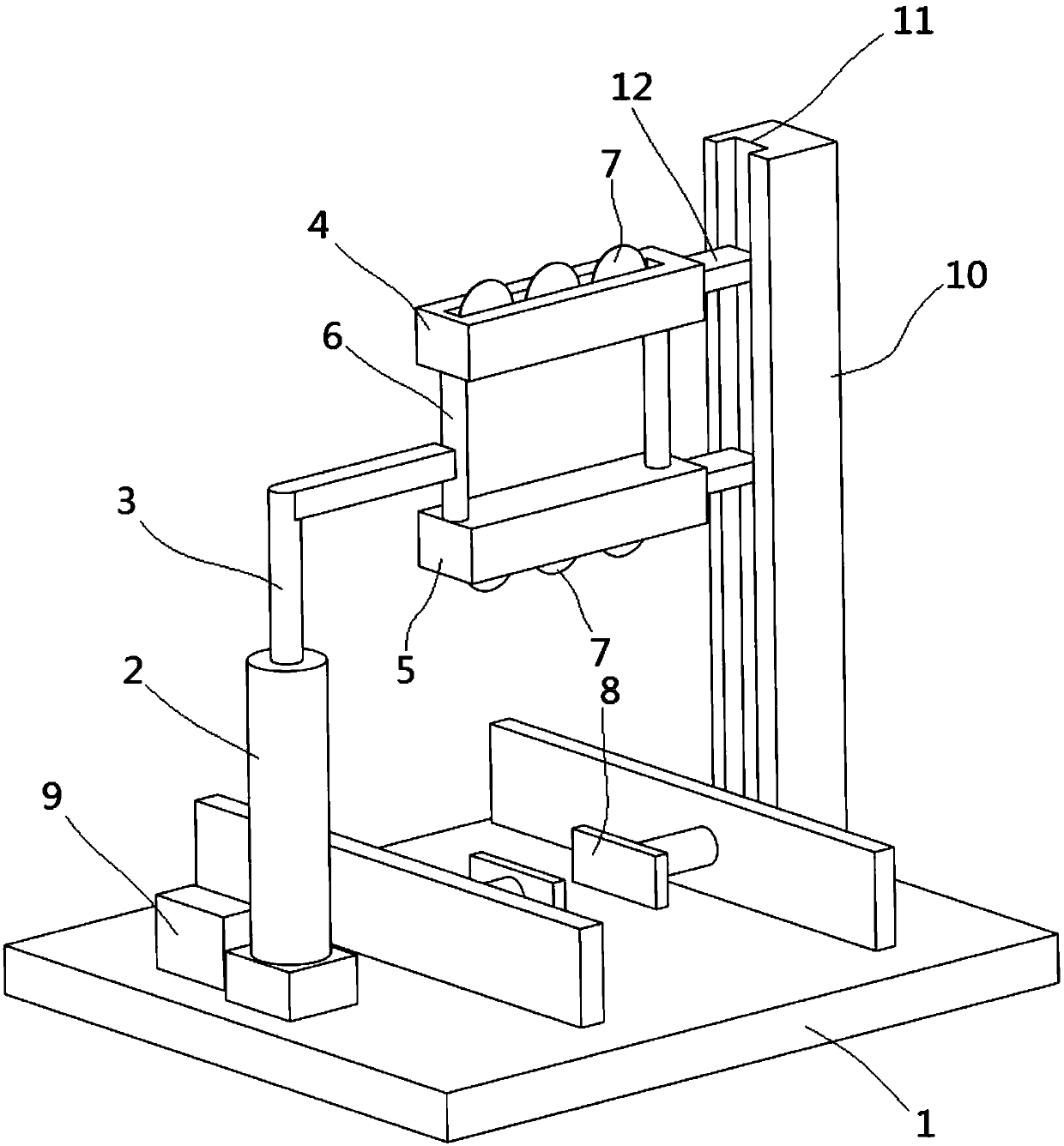
A profile cutting device provided by the present invention includes a mounting base and a lifting shaft rotatably arranged on the mounting base. A cutting mechanism is provided on the top of the lifting shaft, and the cutting mechanism includes a first blade mounting frame and a lifting shaft set The second blade mounting frame, the first blade mounting frame and the second blade mounting frame are provided with a plurality of cutting blades, and the cutting blades are arranged in the first blade mounting frame and the second blade mounting frame through a telescopic mechanism , different processing forms can be adjusted between the first blade mounting frame and the second blade mounting frame. When the profile needs to be cut from the outside, only the cutting blade in the second blade mounting frame is required to cut the profile. When cutting outward from the inside of the profile, the first blade mounting frame and the second blade mounting frame extend outward after entering into the profile, and cut the profile from the inside to the outside. Multiple cutting blades can increase the contact area between the blade and the profile to avoid stress concentration.

Description

technical field [0001] The invention relates to the field of profile processing, in particular to a profile cutting device. Background technique [0002] Profiles are widely used in the field of construction and mechanical structures. The construction speed of profiles is fast, the floor space is small, and it is suitable for all-weather construction, which is less affected by climate conditions. The construction speed of the steel profile is about 2-3 times of the construction speed of the concrete structure, the capital turnover rate is doubled, and the financial cost is reduced, thereby saving investment. [0003] In actual use, the profile needs secondary processing such as cutting. Due to the special structure of the profile, there is an empty groove on the profile, so that there is no support device inside the profile at some positions, and no internal support can be obtained. When cutting, because the diameter of the existing cutting blade is too large, the contact a...

Claims


Application Information

Patent Timeline
Patent Type & Authority Applications(China)
IPC IPC(8): B26D1/18B26D7/26
CPCB26D1/18B26D7/2628
Inventor 杨紫菱
Owner 扬州丽合华工程建设有限公司
Learn More