Special cleaning system for PDC drill bit

A cleaning system and drill bit technology, applied to the cleaning method using tools, cleaning methods using liquid, cleaning methods and utensils, etc., can solve the problems of water reduction, trouble, and high cleaning costs, so as to reduce cleaning costs and improve cleaning Efficiency, the effect of ensuring stability

Inactive Publication Date: 2018-02-23
QIDONG TIANSHAN TOOLS CO LTD
View PDF1 Cites 0 Cited by
  • Summary
  • Abstract
  • Description
  • Claims
  • Application Information

AI Technical Summary

Problems solved by technology

[0007] In the prior art, because the drill bit has been drilling underground for a long time, there will be a large amount of impurities on the surface after use. If it is not removed, it is easy to accelerate the wear of the drill bit and reduce the service life of the drill bit. Usually, the staff removes the drill bit. Cleaning and then reinstalling is cumbersome and less efficient
[0008] After searching, the patent CN204620562U discloses a special cleaning system for PDC drill bits, which includes a base, a rotating shaft, and a disc. The base is provided with casters with brakes, and the bottom of the disc is provided with a circular groove. The rotating shaft One end is connected to the middle part of the upper surface of the base, the other end of the rotating shaft is located in the circular groove, the disc can rotate around the rotating shaft, and the upper surface of the disc is provided with: the first cleaning box, the second cleaning box, and the third cleaning box, the bottom surfaces of the first cleaning box, the second cleaning box, and the third cleaning box are all provided with drain holes, and the drain holes are connected with drain pipes, and the drain pipes are connected with the The water collection tank is connected, the first cleaning tank is equipped with a water gun and an electric cleaning brush, the second cleaning tank is equipped with an ultrasonic cleaning machine, and the third cleaning tank is filled with cleaning liquid, realizing the design of a special cleaning system for PDC drill bits Reasonable, good cleaning effect and high cleaning efficiency; but the cleaning system has the following defects: 1. It is only suitable for cleaning drill bits of a specific height, not suitable for cleaning drill bits of different heights, and then for batch cleaning of drill bits, Drills of different heights need to be equipped with a specific drill cleaning system, so the cleaning cost is relatively high; 2. Since the disc and the rotating shaft are movably connected, there is a lack of stability between the two, so the disc cannot be guaranteed to be in a horizontal state , can not guarantee the consistent cleaning of each drill bit; 3. Since the water in each cleaning tank will continue to drain outward through the drain hole and then through the drain pipe during the cleaning process, the water in the cleaning tank will continue to decrease. , will affect the cleaning effect; and then in order to ensure the cleaning effect, it is necessary to stop the car and add water to each cleaning tank, but this method cannot meet the continuous cleaning, which will affect the cleaning efficiency

Method used


Image

  • Special cleaning system for PDC drill bit
  • Special cleaning system for PDC drill bit
  • Special cleaning system for PDC drill bit

Examples


Embodiment

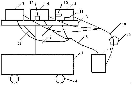
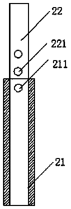
[0024] The present embodiment PDC bit special-purpose cleaning system, as figure 1 As shown, it includes a base 1, a rotating shaft 2, and a disc 3. The base 1 is provided with brake casters 4, and the bottom of the disc 3 is provided with a circular groove, such as figure 2 As shown, the rotating shaft 2 includes a fixed shaft 21 and a telescopic shaft 22, and a pair of pin holes 211 are provided at the upper end of the fixed shaft 21, and several pairs of positioning holes 221 are provided at the lower end of the telescopic shaft 22, which are inserted into the In pin hole 211 and positioning hole 221, fixed shaft 21 and telescopic shaft 22 are fixed; The middle part of the upper surface is connected, and the upper end of the telescopic shaft 22 is located in the circular groove; a support frame 23 is hinged symmetrically on both sides of the upper end of the telescopic shaft 22, and the other end of the support frame 23 is fixedly connected with the bottom surface of the d...


PUM


Abstract

The invention relates to a special cleaning system for PDC drill bits, which includes a base, a rotating shaft, and a disc. The rotating shaft includes a fixed shaft and a telescopic shaft. A pair of pin holes are provided at the upper end of the fixed shaft, and several pairs of positioning holes are provided at the lower end of the telescopic shaft. The lower end of the fixed shaft is connected to the middle part of the upper surface of the base, and the upper end of the telescopic shaft is located in a circular groove; a support frame is symmetrically hinged on both sides of the upper end of the telescopic shaft, and the other end of the support frame is fixedly connected to the bottom surface of the disc through a lock pin; The upper surface of the disc is provided with three cleaning boxes with openings on the upper surface, and the bottom surface of each cleaning box is provided with a drain hole, and a filter is provided at the drain hole; the side of each cleaning box is also provided with a water inlet hole, and the drain hole passes through the drain hole. The pipe is connected with the water collecting tank, and the water inlet hole is connected with the water supply tank through the water inlet pipe. The advantages of the present invention are: the present invention is suitable for cleaning drill bits of different heights, increases the stability of both the disk and the rotating shaft, and can effectively supply water during the cleaning process, thereby ensuring continuous cleaning and improving cleaning efficiency.

Description

technical field [0001] The invention relates to the research field of petroleum machinery and equipment, in particular to a drill bit cleaning device. Background technique [0002] The abbreviation of diamond compact (PDC) drill bit is a drilling tool commonly used in the oil drilling industry. [0003] The performance of PDC products continues to improve. Over the past few years, the quality and type of PDC cutting teeth have changed dramatically. If you compare the teeth of the 1980s with today's teeth, the difference is considerable. Due to the mixing Due to the changes in technology and manufacturing process, the quality and performance of today's cutting teeth are much better, which greatly improves the erosion resistance and impact resistance of the drill bit. [0004] Engineers also optimized the interface between the tungsten carbide substrate and the synthetic diamond to increase the toughness of the cutting teeth. Innovations in layered diamond processing have al...

Claims


Application Information

Patent Timeline
Patent Type & Authority Applications(China)
IPC IPC(8): B08B3/02B08B3/12B08B3/14B08B3/08B08B1/00B08B13/00
CPCB08B3/02B08B1/002B08B3/08B08B3/12B08B3/14B08B13/00
Inventor 戴帅东
Owner QIDONG TIANSHAN TOOLS CO LTD
Why Eureka
Try Eureka