
A bonding reliability experiment device and control method for simulating lateral vibration conditions

A technology of lateral vibration and experimental equipment, which is applied in vibration testing, measuring equipment, testing of machine/structural components, etc., and can solve tensile tests that cannot achieve large displacements, large displacement stretching, and high-frequency vibrations Problems such as loading simulation

Active Publication Date: 2020-02-07
SHANGHAI JIAOTONG UNIV
View PDF12 Cites 0 Cited by
  • Summary
  • Abstract
  • Description
  • Claims
  • Application Information

AI Technical Summary

Problems solved by technology

[0005] China Patent Authorization Announcement No. CN 102252909 B, titled "Tensile Testing Device", discloses a tensile testing device, which is characterized in that it is a four-axis horizontal tensile testing machine using an oil cylinder, clamping assembly and linear guide rails, which can The biaxial tensile test is completed, but the disadvantage is that the high-thrust hydraulic cylinder cannot achieve motion loading of hundreds to thousands of hertz, and cannot achieve fatigue loading
Chinese Patent Publication No. CN 104568591 A, titled "A Biaxial Tensile Test Device", discloses a biaxial tensile test device, which is characterized in that the ends of the four arms of the horizontal positive cross loading slide rail All are equipped with servo cylinders, which can be applied to uniaxial tensile testing machines and biaxial tensile testing machines to realize various test functions, but cannot realize high-frequency vibration loading simulation, and can only realize low-cycle cycle back and forth tensile tests
Chinese Patent Publication No. CN 106053272 A, titled "a wide-band fatigue testing machine", discloses a wide-band fatigue testing machine, which is characterized in that the driving source of the alternating motion of the lower type is used as the loading device of the fatigue testing machine, which can Fatigue experiments with large driving forces, large displacements, and wide frequency bands can be achieved, but the shortcoming is that relying on a single electromagnetic drive device cannot achieve the requirements of large displacement tensile tests coupled with micro-amplitude vibrations
Chinese Patent Publication No. CN 106813981 A, titled "A Tensile Fatigue Tester", discloses a tensile fatigue tester, which is characterized in that it is driven by an electric vibrator installed below to realize fatigue experiments on tiny test pieces , its disadvantage is that it is only suitable for a single loading test of a small test piece, and cannot achieve a large displacement tensile test

Method used


Image

  • A bonding reliability experiment device and control method for simulating lateral vibration conditions
  • A bonding reliability experiment device and control method for simulating lateral vibration conditions
  • A bonding reliability experiment device and control method for simulating lateral vibration conditions

Examples


Embodiment 1

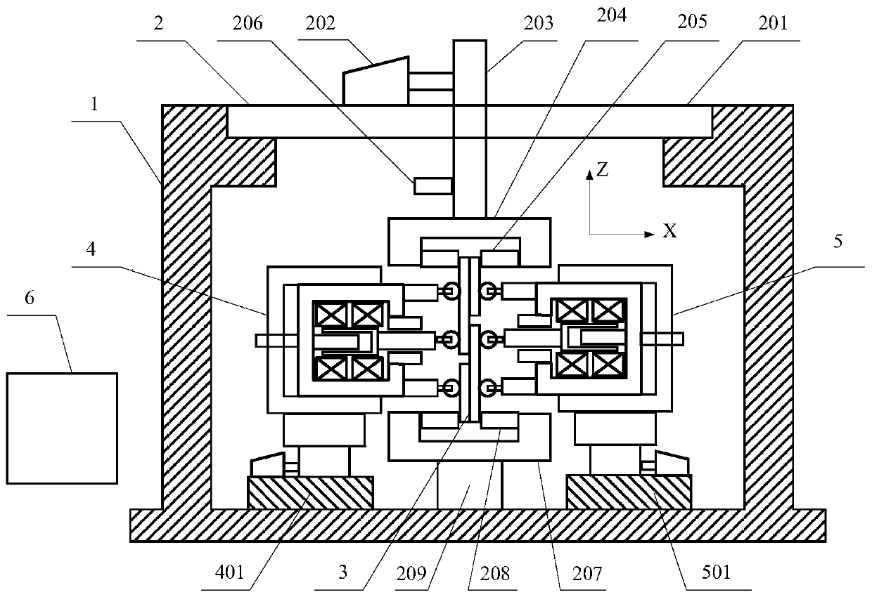
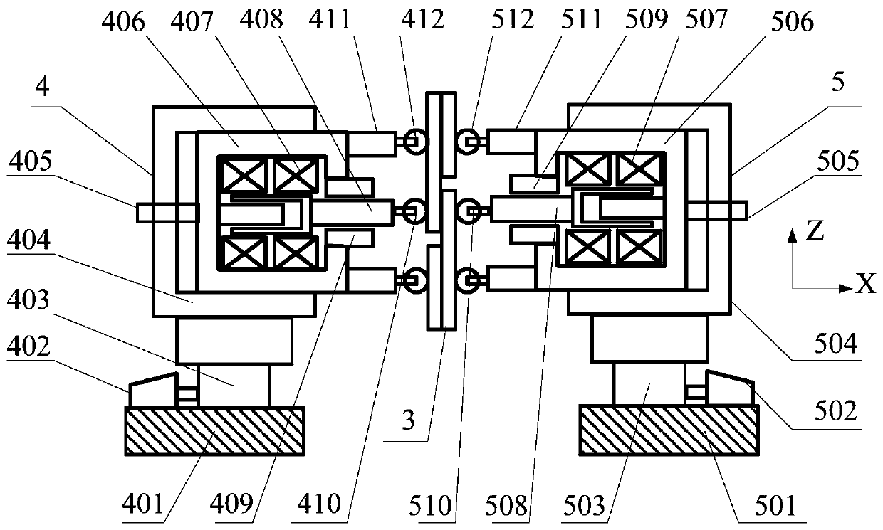
[0061] Such as figure 1 As shown, a bonding reliability experiment device that simulates lateral vibration conditions includes a frame body 1, a main loading platform 2, a bonding test sample 3, a left vibration loading platform 4, a right vibration loading platform 5, and a central control 器6 consists of. It is characterized in that: the frame body 1 mainly plays a role of stabilization and structural support, and it wraps other parts of the testing machine inside. Due to the force and vibration, it should be consolidated with the bottom surface during use. A main loading platform 2 is arranged on the upper part of the frame fuselage 1, wherein the main loading platform 2 includes a main loading platform base 201 arranged on the upper part of the frame fuselage 1, a main loading drive motor 202 located on the main loading platform base 201, and a main The main loading cantilever 203 connected to the loading drive motor 202, the upper chuck 204 connected to the end of the main l...

Embodiment 2

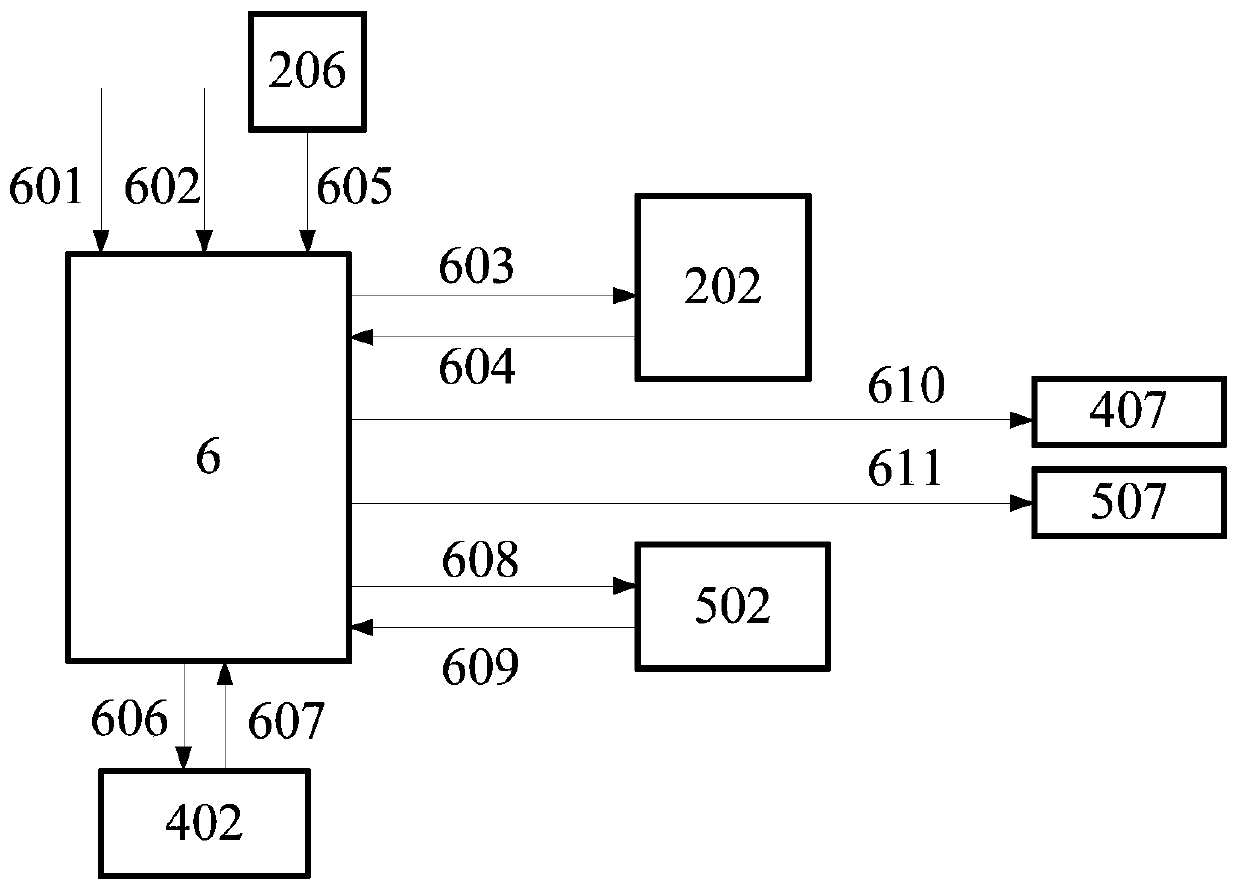
[0064] Such as image 3 As shown, a control method of a bonding reliability experimental device that simulates lateral vibration conditions is:


PUM


Abstract

The invention discloses a bonding reliability testing device, especially relates to a bonding reliability testing device of simulating the transverse vibration condition, and brings forward a controlmethod according to actual conditions. The testing device comprises a framework body, a main loading platform, a bonding testing sample piece, a left / right vibration loading platform and a central controller. Vibration generated by the left / right vibration loading platform in the frame body acts on the bonding testing sample piece. The vibration loading platform is driven by a motor, and Z-direction loading of a main loading platform is followed. The control method of the testing device comprises steps of receiving instruction and feeding back information, conducting coordination control of each part of the testing device and the like. Through Z-direction following of the main loading axis and transverse vibration loading of the test piece, tension property testing under the transverse vibration condition is realized. The testing device is more suitable for performance testing in the actual service environment and can be widely applied to tension testing and fatigue testing of bondingreliability testing under transverse vibration condition.

Description

Technical field [0001] The invention relates to the field of bonding reliability experiments, in particular to a bonding reliability experiment device and an experiment method thereof that simulate lateral vibration working conditions. Background technique [0002] Gluing technology is widely used in the connection and sealing of various contact surfaces. It has the characteristics of reliable connection and good sealing. It has a very wide range of applications in actual production such as airplanes and automobiles. In particular, in the assembly process of the engine, a large number of glue joints are used to seal the two processed surfaces, which affects the sealing and safety of the engine. Bonding reliability is a key indicator to measure the performance of the engine's bonding and sealing. The failure of the bonding and sealing will cause leakage. Improving the bonding and sealing of the machined surface is of great significance to ensuring the service performance of the en...

Claims


Application Information

Patent Timeline
Patent Type & Authority Patents(China)
IPC IPC(8): G01N3/08G01N3/32G01M7/02
CPCG01M7/022G01N3/08G01N3/32
Inventor 金隼张雪萍刘顺陈坤
Owner SHANGHAI JIAOTONG UNIV
Learn More