
Turning-milling complex eccentric cutter handle

A tool holder and eccentric technology, which is applied in the field of turning-milling compound eccentric tool holder, can solve the problems of affecting product accuracy, easy to produce errors, small tool holder design, etc., and achieve the effect of simple design structure, strong functionality and improved quality

Pending Publication Date: 2018-02-16
广东钶锐锶数控技术股份有限公司
View PDF21 Cites 0 Cited by
  • Summary
  • Abstract
  • Description
  • Claims
  • Application Information

AI Technical Summary

Problems solved by technology

[0002] The traditional turning and milling compound tool holder includes the machine bed, the spindle box, the spindle, the spindle axis, the tool holder and the tool. Generally, the traditional tool holder is connected to the spindle. The traditional equipment tool holder is designed to be small, and the tool is connected to the tool holder The center of the bottom is rotated to grind the workpiece. During the processing of the workpiece, due to the gap between the spindle axis and the spindle, the tool shakes during the processing, which makes the outer surface of the workpiece produce concave lines, and the traditional equipment is changing the tool. Errors are easy to occur in the process, which affects the accuracy of the product. The above problems need to be improved on the traditional equipment, so how to design a new type of turning-milling compound eccentric tool holder has become a problem we need to solve
[0003] At present, it is difficult to eliminate the vibration of the tool during the machining process of the turning and milling machine, and because the milling machine has a large margin and a large machining diameter, the turning range of the tool is large and the tool strength is high. The position of the large diameter of the tool and the processing The strength is difficult to adjust, and it is difficult to meet the requirements of size and appearance precision in the process of machining, turning and milling

Method used


Image

  • Turning-milling complex eccentric cutter handle
  • Turning-milling complex eccentric cutter handle
  • Turning-milling complex eccentric cutter handle

Examples


Embodiment Construction

[0021] In order to fully understand the technical content of the present invention, the technical solutions of the present invention will be further introduced and illustrated below in conjunction with specific examples, but not limited thereto.

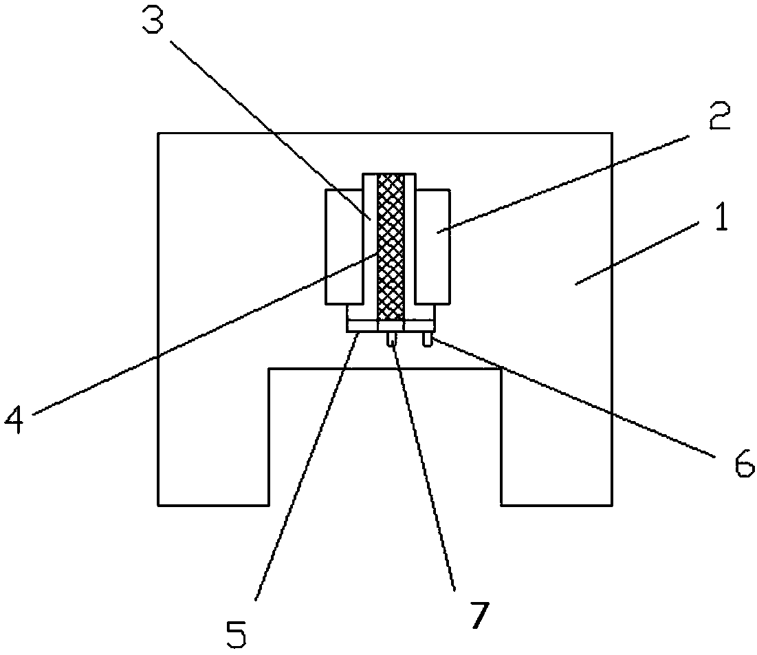
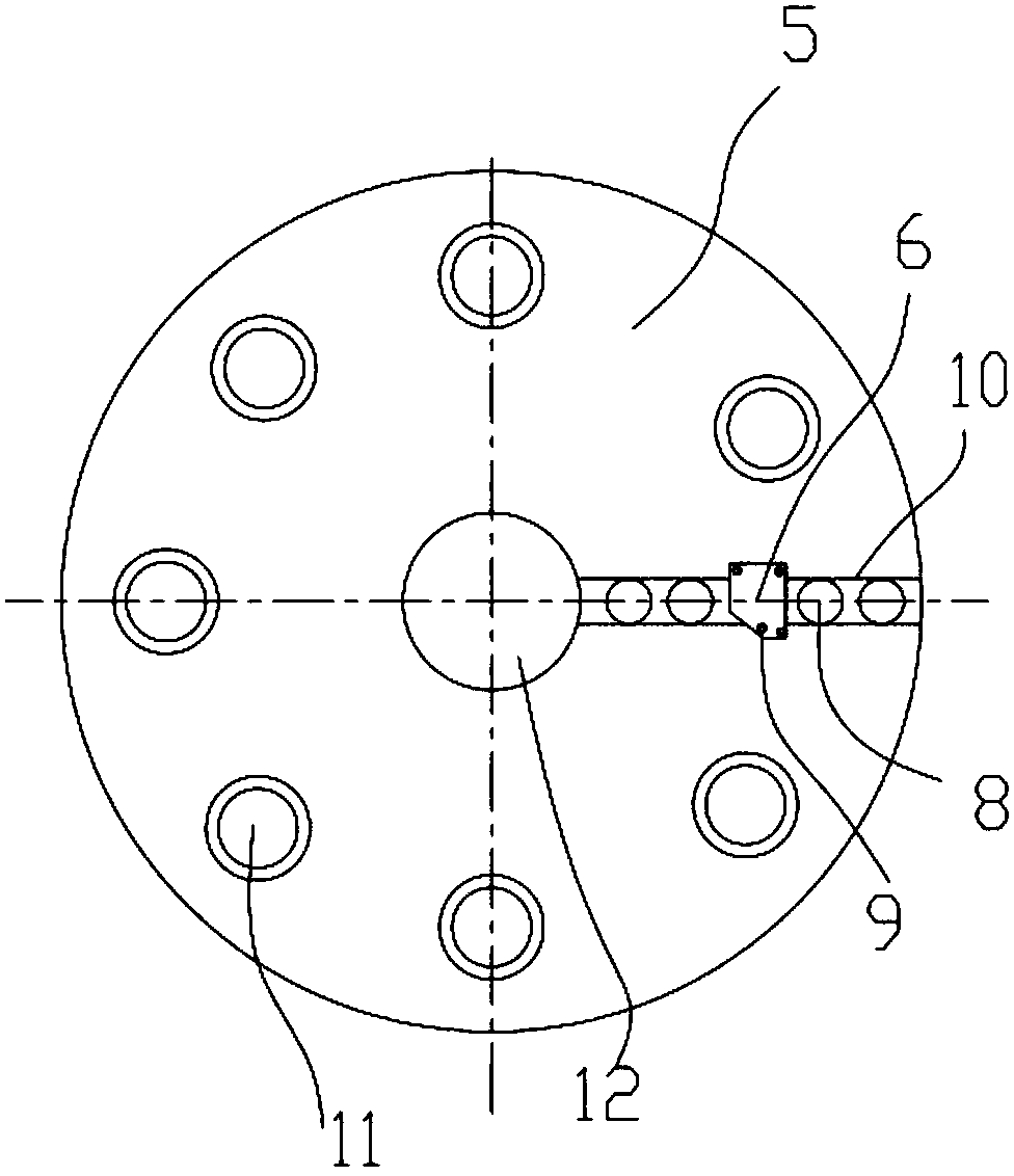
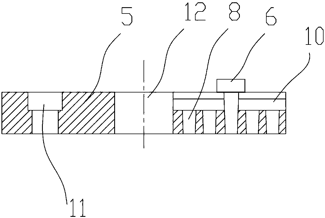
[0022] see Figure 1-3 As shown, the present invention provides a technical solution: a turning-milling compound eccentric tool holder 5, including a machine bed 1, a spindle box 2, a spindle 3, a spindle axis 4, a tool handle 5 and a tool 6, and a machine bed 1 The interior of the spindle box 2 is provided with the spindle box 2, the center of the spindle box 2 is provided with the spindle axis 4, the outer surface of the spindle axis 4 is provided with the spindle 3, the bottom of the spindle 3 is fixedly connected to the tool handle 5, and the center of the tool handle 5 is positioned A cutter 6 is eccentrically connected to the outer side of the spindle axis 4 and the center of the bottom of the handle 5 .

[0023] The tool hand...


PUM


Abstract

The invention discloses a turning-milling complex eccentric cutter handle, which comprises a machine tool bed, a main shaft box, a main shaft, a main shaft axis, a cutter handle and a cutter. The mainshaft box is arranged in the machine tool bed; the main shaft axis is arranged in the center of the main shaft box; the main shaft is arranged on an external circular surface of the main shaft axis in a sleeving way; the cutter handle is fixedly connected to the bottom part of the main shaft; the center of the cutter handle is positioned in the main shaft axis; the cutter is eccentrically connected to the outer side of the circle center of the bottom part of the cutter handle; a flange plate end face of the cutter tightly fits a connecting end face of the main shaft in a seamless way; the cutter handle is fixedly connected onto the main shaft; the cutter is arranged and fixed to a radial slot, and an eccentric position of the cutter in the radial slot can be adjusted, so that the rigidityof the cutter is improved, meanwhile, errors easily occur during a cutter process are eliminated, and the surface of a produced workpiece is smoother; the turning-milling complex eccentric cutter handle is provided with a milling cutter handle avoidance site, so that a milling cutter handle can be used simultaneously in a noninterference way; and the integrated design structure is simple, the functionality is good, and the quality of products is greatly improved through the equipment.

Description

technical field [0001] The invention relates to the technical field of mechanical production and processing equipment, in particular to a turning-milling compound eccentric tool holder. Background technique [0002] The traditional turning and milling compound tool holder includes the machine bed, the spindle box, the spindle, the spindle axis, the tool holder and the tool. Generally, the traditional tool holder is connected to the spindle. The traditional equipment tool holder is designed to be small, and the tool is connected to the tool holder The center of the bottom is rotated to grind the workpiece. During the processing of the workpiece, due to the gap between the spindle axis and the spindle, the tool shakes during the processing, which makes the outer surface of the workpiece produce concave lines, and the traditional equipment is changing the tool. Errors are easy to occur in the process, which affects product accuracy. The above problems require improvement of tra...

Claims


Application Information

Patent Timeline
Patent Type & Authority Applications(China)
IPC IPC(8): B23Q3/12
CPCB23Q3/12
Inventor 蒙昌敏邹仕生
Owner 广东钶锐锶数控技术股份有限公司
Learn More