
Differential Reference Buffer

A voltage buffer and differential reference technology, applied in instruments, adjusting electrical variables, and control/regulating systems, etc., can solve the problems of low setup speed, high power consumption of differential reference voltage buffers, and large chip area, and achieve functional The effect of reducing power consumption, reducing output equivalent impedance and improving energy efficiency

Active Publication Date: 2020-08-07
SHANGHAI BEILING
View PDF5 Cites 0 Cited by
  • Summary
  • Abstract
  • Description
  • Claims
  • Application Information

AI Technical Summary

Problems solved by technology

[0004] The technical problem to be solved by the present invention is to overcome the defects of large power consumption, large chip area occupation, and low establishment speed of the differential reference voltage buffer in the prior art, and provide a method that can reduce the equivalent impedance of the reference voltage output, improve the current efficiency, Differential reference voltage buffer that also enables faster reference voltage settling

Method used


Image

  • Differential Reference Buffer

Examples


Embodiment Construction

[0024] The present invention is further illustrated below by means of examples, but the present invention is not limited to the scope of the examples.

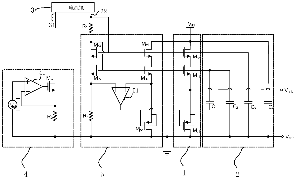
[0025] Such as figure 1 As shown, a differential reference voltage buffer includes a current mirror 3 , a reference current generation part 4 , a control part 5 , a decoupling part 2 and a replica buffer output part 1 .

[0026] Wherein, the copy buffer output part 1 includes a first NMOS transistor M n1 , the second NMOS tube M n2 and the first PMOS transistor M p1 ; The decoupling part 2 includes a first capacitor C 1 , the second capacitance C 2 , the third capacitor C 3 and the fourth capacitor C 4 ; The control part 5 includes a first operational amplifier 51, a first resistor R 1 , the third NMOS tube M n3 , the fourth NMOS tube M n4 , the fifth NMOS tube M n5 , the sixth NMOS tube M n6 , the second PMOS tube M p2 and the third resistor R 3 ; The reference current generation part 4 includes a second operatio...


PUM


Abstract

The invention discloses a differential reference voltage buffer. The buffer comprises a replication buffer output part which comprises a first NMOS transistor and a first PMOS transistor which share one bias current, the source electrode of the first NMOS transistor and the source electrode of the first PMOS transistor are connected and output positive reference voltage, and the drain electrode ofthe first PMOS transistor outputs negative reference voltage. According to the differential reference voltage buffer, by means of innovation of a circuit structure, by adopting the mode that the source electrodes of the first MPOS transistor and the first NMOS transistor are connected in parallel for output, positive reference voltage output equivalent impedance is lowered, the reference voltagebuildup speed is higher at the same time of improving the current efficiency, the energy consumption efficiency is improved, and the power consumption is lowered.

Description

technical field [0001] The invention relates to the field of integrated circuits, in particular to a differential reference voltage buffer. Background technique [0002] The reference voltage generally refers to a highly stable voltage used as a voltage reference in a circuit, and is also called a reference voltage. Precise and stable reference voltages are required in many integrated circuits and circuit units, such as D / A converters, A / D converters, linear regulators and switching regulators. [0003] Due to the rapid development of modern communication systems, more challenges have been put forward for the design of high-speed, high-precision analog-to-digital converters. While ensuring system performance, it is also necessary to make the system power consumption as low as possible. The differential reference voltage buffer, also known as the differential reference voltage buffer circuit, is an integral part of the A / D converter and plays a decisive role in system perfor...

Claims


Application Information

Patent Timeline
Patent Type & Authority Patents(China)
IPC IPC(8): G05F3/26
CPCG05F3/267
Inventor 张辉李丹王海军
Owner SHANGHAI BEILING
Learn More