
Energy absorbing box provided with concave polygonal section and provided with fold at one end

A concave polygon and energy-absorbing box technology, which is applied in vehicle safety arrangements, bumpers, non-rotational vibration suppression, etc., can solve the problems that are not suitable for the use of energy-absorbing boxes and cannot provide ultra-high specific energy absorption rate

Inactive Publication Date: 2018-02-13
李洋
View PDF6 Cites 2 Cited by
  • Summary
  • Abstract
  • Description
  • Claims
  • Application Information

AI Technical Summary

Problems solved by technology

Then, because the concave polygonal tube has a high load uniformity coefficient when it is compressed, and it is more inclined to the overall failure form (rather than progressive buckling failure), it cannot provide the theoretical super high specific energy absorption rate, so it is not suitable Use as a crash box

Method used


Image

  • Energy absorbing box provided with concave polygonal section and provided with fold at one end
  • Energy absorbing box provided with concave polygonal section and provided with fold at one end
  • Energy absorbing box provided with concave polygonal section and provided with fold at one end

Examples


Embodiment 1

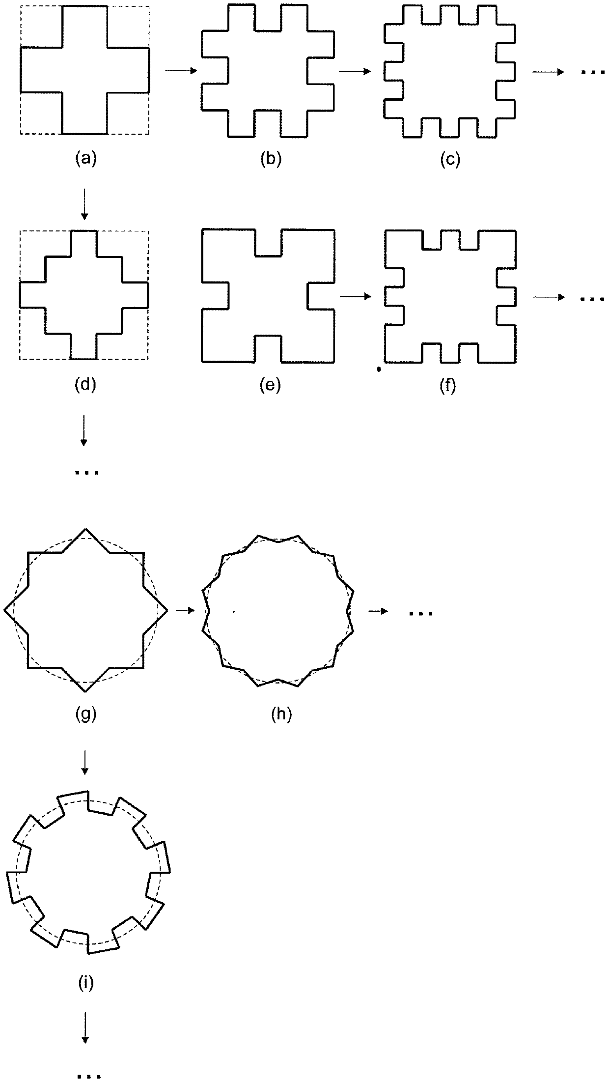
[0022] Embodiment 1: with figure 1 (a) An embodiment of a constant-section crash box with a crease at one end of the middle section as an example.

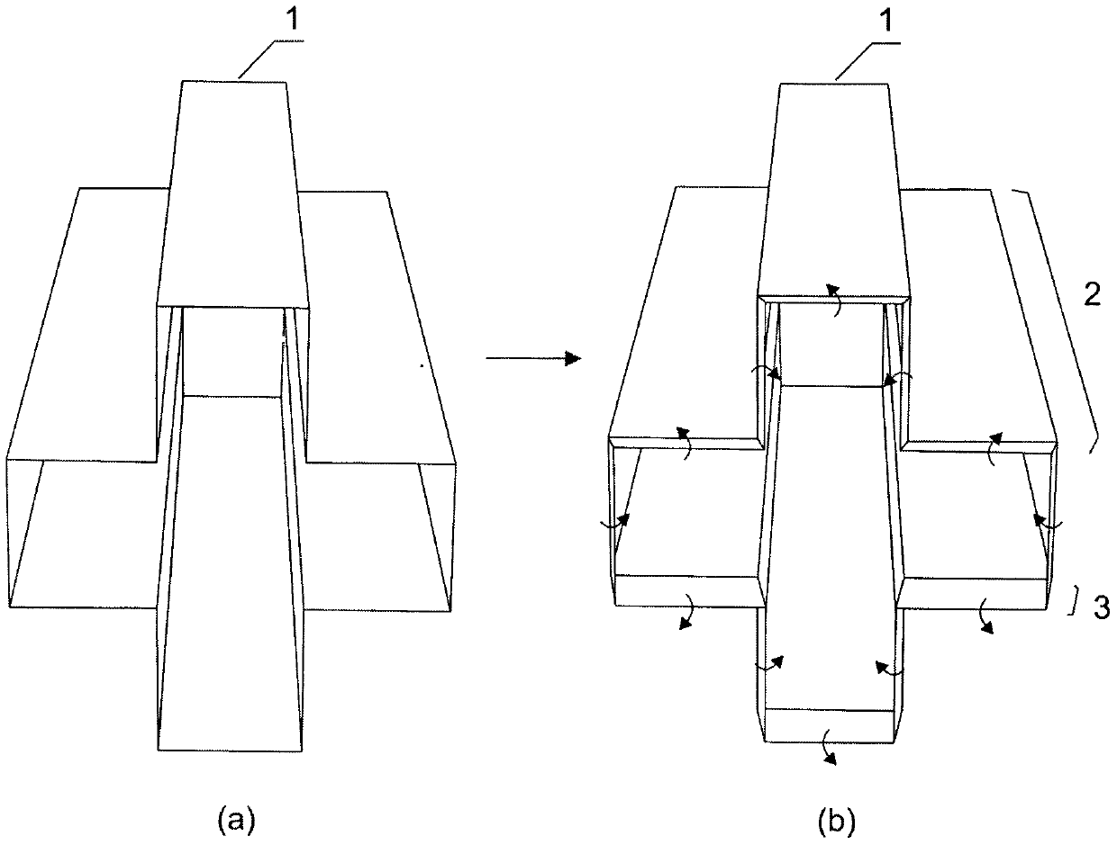
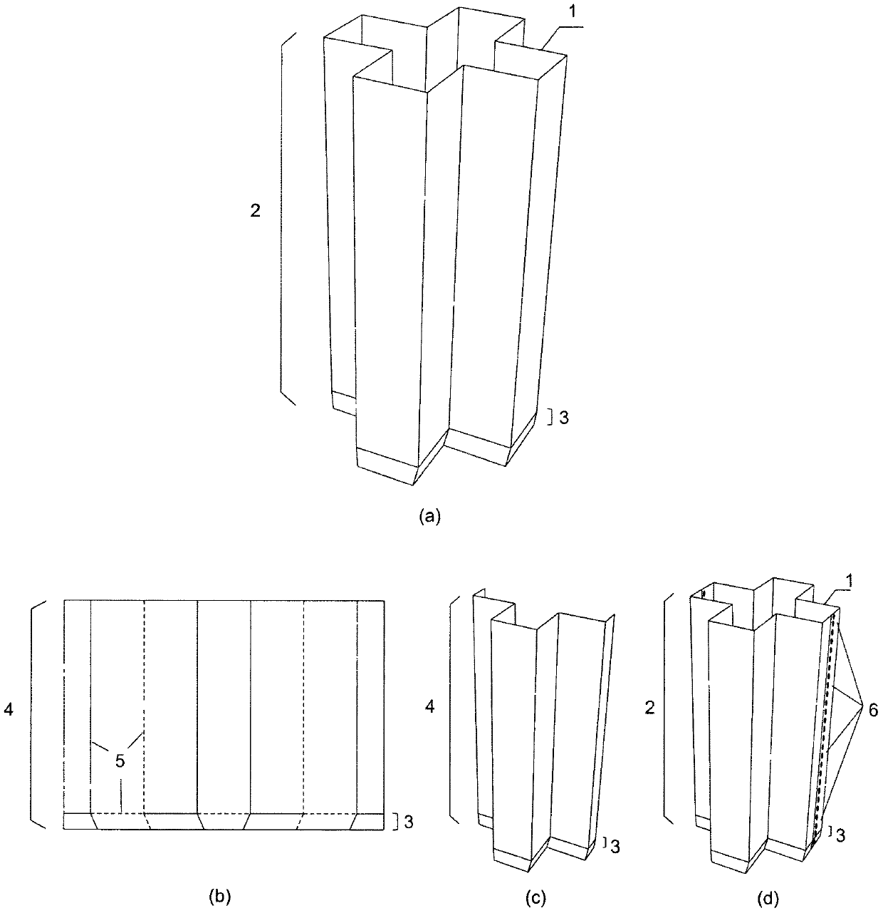
[0023] The first step is to determine the cross-sectional form, to figure 1 (a) The middle section as an example. The second step is to choose the processing method, taking the use of plate pressing as an example. There are roughly two ways to use plate pressing: the first is through traditional methods such as pressing and welding. figure 2 The ordinary concave polygonal cross-section pipe shown in (a), and then one end thereof is bent to form a guiding crease 3, thereby forming an energy-absorbing box 2, as figure 2 (b); The second is to press two (or several) shells 4 respectively by a mold with a concave polygonal cross section and creases, such as image 3 As shown in (c), then two (or several) shells 4 are connected (welded) together through a fixed point 6 to form a complete energy-absorbing box 2, as image 3 (d), w...

Embodiment 2

[0024] Embodiment 2: An embodiment of a constant-section crash box with a crease at one end formed with other different cross-sections.

[0025] Figure 4 8 and 11 are respectively composed of section 7 ( figure 1 (b)) and 10( figure 1 (h)) Schematic diagram of the formed crash box, 9 and 12 are its creases. These two cross-sections and other concave polygonal cross-sections can be made into corresponding crash boxes in the same manner as in Embodiment 1.

Embodiment 3

[0026] Embodiment 3: with figure 1 (d) An embodiment of a variable cross-section crash box with a crease at one end of the middle cross-section as an example.

[0027] The variable-section crash box design helps to increase the compression stroke of the crash box. Figure 5 , based on section 13( figure 1 (d)), 14 is its corresponding constant-section crash box, and 16 and 18 are corresponding variable-section crash boxes formed in different ways. Figure 6 are the expanded plan views respectively. Manufacturing method refers to embodiment 1.


PUM


Abstract

The invention discloses an energy absorbing box provided with a concave polygonal section and provided with a fold at one end and belongs to the field of vehicle structures including automobiles, trains and the like. According to the purpose, kinetic energy is absorbed through stress deformation of the structure during colliding. The energy absorbing box is characterized in that the concave polygon serves as the section, the fold is introduced to one end of the structure, and therefore the novel energy absorbing box is formed. The energy absorbing box has the beneficial effects that due to thefact that the concave polygonal section is used, more edges and corners are introduced into the structure, the energy absorbing potential on the structural theory is improved, meanwhile, the fold isled to one end of the structure, and therefore the structure can be led to generate a designed stable and gradual deformation manner during stress, and the ultrahigh specific energy absorption rate (increased by 100% to 200% than that of a traditional energy absorbing box) is achieved. Due to introduction of the fold, the structural rigidity is lowered, and the energy absorption box can have the low-load uniformity coefficient at the same time. By means of the energy absorbing box, the fold shape is convenient to form, the surface of the whole structure is a developable surface, the whole structure can be machined and formed directly through a piece (or multiple pieces) of thin flat plates, and therefore machining can be more convenient and more accurately.

Description

technical field [0001] The invention belongs to the technical field of structural manufacture of vehicles such as automobiles and trains, and is a device for absorbing impact kinetic energy in the event of impact. Background technique [0002] Traffic safety is an important issue in people's daily life. The structure in the vehicle has better crashworthiness to provide better protection for the driver and passengers in the event of a crash. To absorb the kinetic energy in a collision, crash boxes are usually installed in front of cars and locomotives. The energy-absorbing box is compressed and flattened during the impact, and can produce high resistance in the process, so that the car or train can be decelerated to achieve the purpose of buffering and absorbing energy. [0003] An ideal crash box needs to meet the following conditions: (1) high specific energy absorption rate (the specific energy absorption rate is defined as the ratio of the maximum capacity that the cras...

Claims


Application Information

Patent Timeline
IPC IPC(8): F16F15/04B60R19/02
CPCF16F15/04B60R19/023
Inventor 李洋由衷
Owner 李洋
Learn More