Backward projection imaging method based on random reference average cross-correlation information
A technology of back projection and imaging method, applied in the field of radar image processing and back projection imaging based on random reference average cross-correlation information, can solve the problems of high side lobes and interference, poor imaging performance, etc., to achieve the suppression of side lobes and Effects of interference, increased robustness, avoided performance differences
- Summary
- Abstract
- Description
- Claims
- Application Information
AI Technical Summary
Problems solved by technology
Method used
Image

Examples
specific Embodiment approach 1
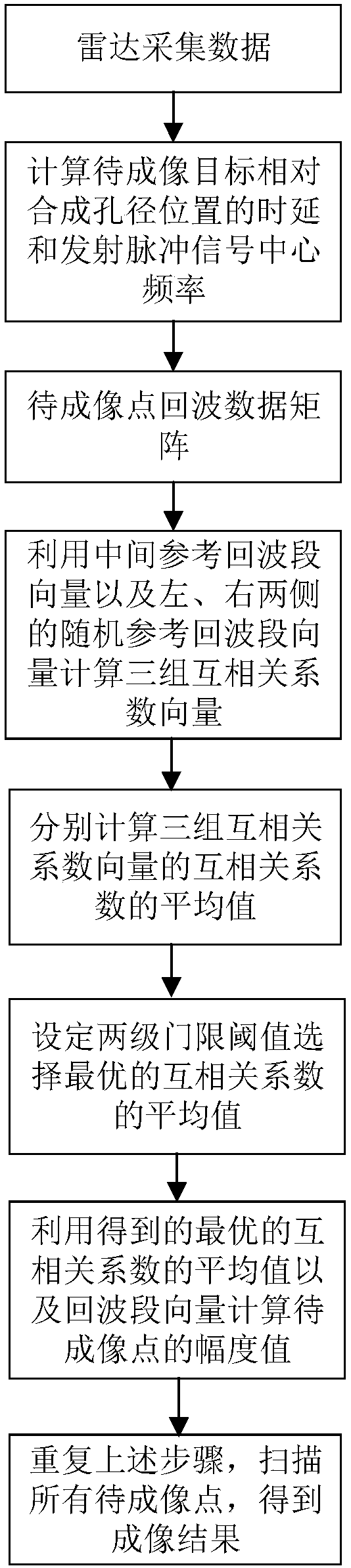
[0060] Specific implementation mode 1. Combination figure 1 This embodiment will be described. A back projection imaging method based on random reference average cross-correlation information, the specific process is as follows:
[0061] Step 1, the data collected by the radar is obtained by calculating the time delay of the target to be imaged relative to the position of the synthetic aperture and the center frequency of the transmitted pulse signal to obtain the echo data matrix of the point to be imaged;
[0062] Step 2, using the middle reference echo segment vector and the random reference echo segment vectors on the left and right sides to calculate three sets of cross-correlation coefficient vectors, and respectively calculate the average value of the cross-correlation coefficients of the three sets of cross-correlation coefficient vectors;
[0063] Step 3, select the average value of the optimal cross-correlation coefficient by setting the two-level threshold;
[006...
specific Embodiment approach 2
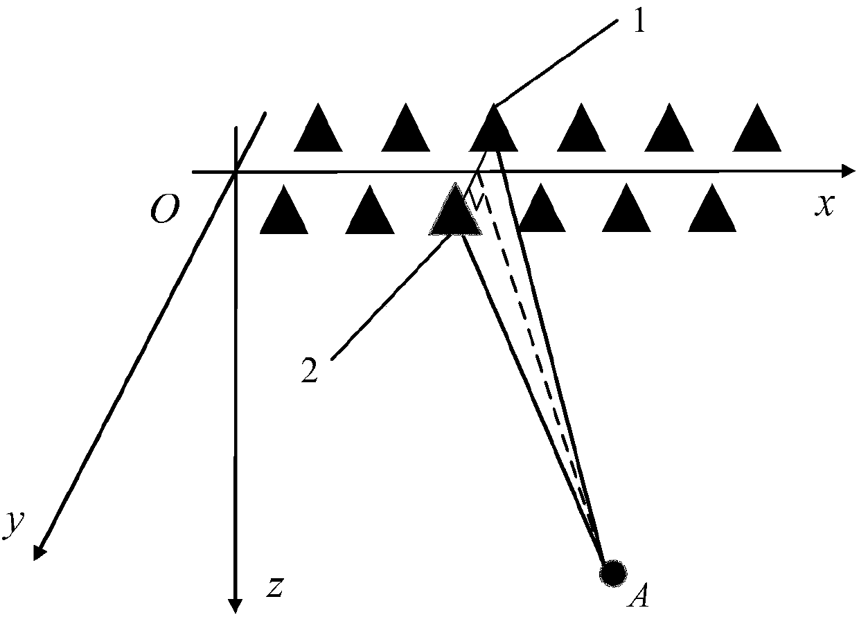
[0066] Specific implementation mode two, see figure 2 and 3 This embodiment will be described. This implementation mode is a further description of the specific implementation mode 1. Step 1 is specifically:
[0067] Step 11) The kth synthetic aperture transmitting antenna T k The position is (x k ,Δy / 2,0), the kth synthetic aperture receiving antenna R k The position is (x k ,-Δy / 2,0), the position of the target A to be imaged is (x A ,0,z A );
[0068] Step 12) The time delay τ of the target A to be imaged relative to the position of the kth synthetic aperture A,k for
[0069]
[0070] The number of synthetic apertures is N p , the time delay vector from the target to be imaged A to each synthetic aperture position:
[0071] Step 13) The center frequency of the transmitted signal of the target A to be imaged is f 0 , the equivalent sampling frequency is f s , take each delay position as the center, take the echo data of length S as the echo data to be proc...
specific Embodiment approach 3
[0078] Specific implementation mode three. This implementation mode is a further description of specific implementation mode one. Step 2 is specifically:
[0079] Step 21) is the middle reference echo band vector, and then randomly select a left reference echo band vector on the left side of the middle reference echo band Randomly select a right reference echo band vector on the right side of the middle reference echo band
[0080] Step 22) According to the correlation between the echo segment vector obtained at each synthetic aperture position and the middle reference echo segment vector, the left reference echo segment vector and the right reference echo segment vector, three sets of cross-correlation coefficient vectors are calculated and Among them, the cross-correlation coefficient ρ A,1k , ρ A,2k , ρ A,3k is calculated using the Pearson correlation coefficient:
[0081]
[0082]
[0083]
[0084] The Cov(i,j) function represents the covariance of vec...
PUM
 Abstract
Description
Claims
Application Information
 - R&D
- Intellectual Property
- Life Sciences
- Materials
- Tech Scout
- Unparalleled Data Quality
- Higher Quality Content
- 60% Fewer Hallucinations
Browse by: Latest US Patents, China's latest patents, Technical Efficacy Thesaurus, Application Domain, Technology Topic, Popular Technical Reports.
© 2025 PatSnap. All rights reserved.Legal|Privacy policy|Modern Slavery Act Transparency Statement|Sitemap|About US| Contact US: help@patsnap.com