
A method for continuous laser shock fusion injection of fine particles by forming injection force with laser shock energy

A technology of fine particle and laser shock, applied in the direction of metal material coating process, coating, etc., can solve the problems of restriction and difficulty in realizing the injection of fine particles, and achieve the effect of strong adaptability

Active Publication Date: 2019-08-27
JIANGSU UNIV
View PDF5 Cites 0 Cited by
  • Summary
  • Abstract
  • Description
  • Claims
  • Application Information

AI Technical Summary

Problems solved by technology

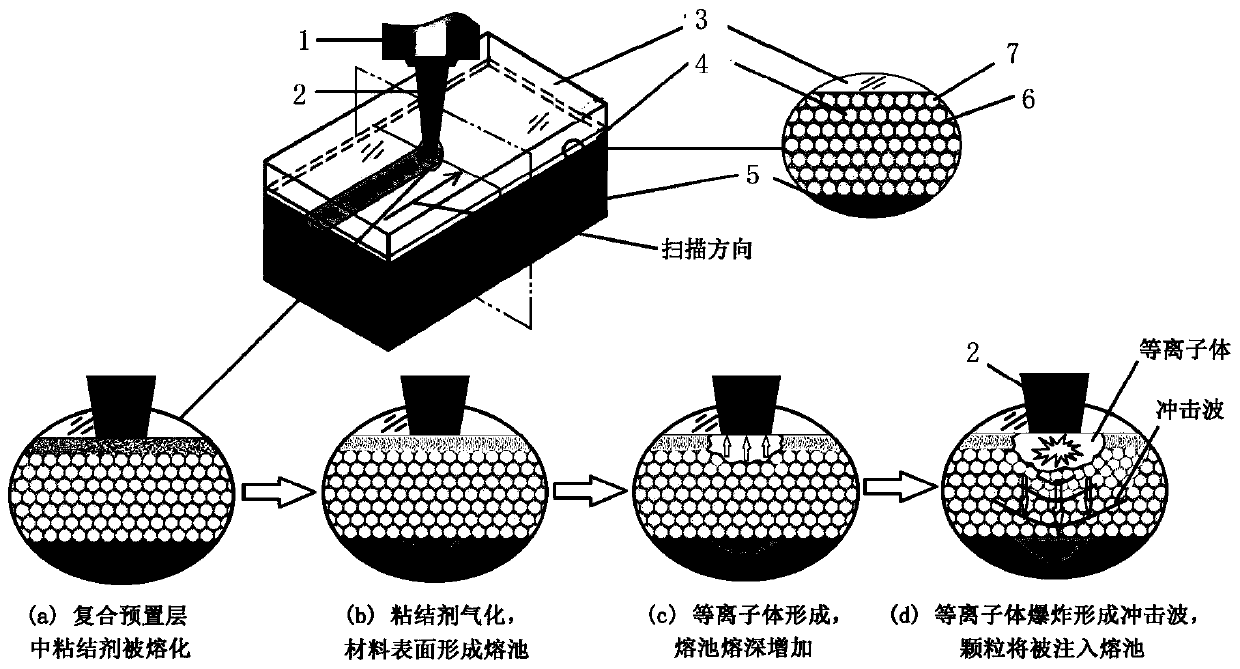
[0004] Aiming at the problem that the existing laser melt injection particle enhancement technology is difficult to achieve fine particle melt injection, which further restricts the application of fine particles, a reinforcing material with excellent modification characteristics, in the field of laser melt injection particle enhancement technology, the present invention provides a A method for continuous laser shock fusion injection of fine particles by forming injection force with laser shock energy

Method used


Image

  • A method for continuous laser shock fusion injection of fine particles by forming injection force with laser shock energy
  • A method for continuous laser shock fusion injection of fine particles by forming injection force with laser shock energy
  • A method for continuous laser shock fusion injection of fine particles by forming injection force with laser shock energy

Examples


Embodiment

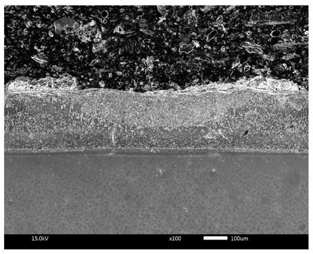
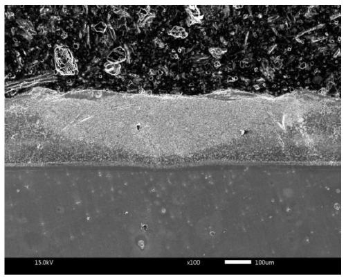
[0038] The material to be modified is an aluminum-silicon coating on the surface of a nickel-based superalloy (its melting point is about 1420°C), the binder is sodium chloride (its melting point is 891°C, its boiling point is 1413°C), and the fine particles to be melted are average Cerium oxide with a particle size of 1 μm (its melting point is 2397°C, when the particle size exceeds 100nm, its melting point basically does not decrease with the decrease of the particle size), the thickness of the composite pre-layer is 0.5mm; fiber laser is used in the melting process, The laser process parameters are 450W power, 1250mm / min scanning speed, 0.8mm spot diameter, and zero defocus; the constrained layer is covered with a coated quartz glass constrained layer on the composite preset layer.


PUM

PropertyMeasurementUnit
particle diameteraaaaaaaaaa
thicknessaaaaaaaaaa

Abstract

A method for continuous laser-shock melting and injection of fine particles by formation of an injection force with laser-shock energy, wherein a continuous laser beam is transmitted through a constraining layer to scan a composite layer precoated on the surface of a material to be modified and composed of a mixture of a binder capable of inducing a laser shock wave effect and fine particles to be melted and injected. Parameters such as melting points and boiling points of the binder, the material to be modified, and the fine particles to be melted and injected are appropriately coordinated, realizing gasification of the binder through induction by the continuous laser beam to form a laser shock wave so as to inject the fine particles to be melted into a molten pool on the surface of the material to be modified, thereby forming a fine particle-reinforced composite material layer in situ. With the method, the fine particles and the material to be modified in the composite material layer obtained on the surface of the material to be modified are metallurgically bonded, resolving the technical issue in the prior art of difficulty in melting and injecting fine particles. Further, the method features deeper injection depth, a small microstructure, uniform distribution of reinforcing particles, and is not restricted by the plasticity of the material to be modified.

Description

technical field [0001] The invention belongs to the technical field of laser surface treatment, and relates to a method for laser melting and injection of reinforced particles, in particular to a method for forming injection force by laser shock energy to realize continuous laser shock and injection of fine particles. Background technique [0002] Laser melt injection particle enhancement technology is an advanced laser surface treatment technology. The basic principle is: during the laser melting injection process, the high-power-density laser beam forms a molten pool on the metal surface, and at the same time, the reinforcing particles are directly injected into the molten pool. During the rapid cooling of the molten pool, the injected particles have no time to melt and are " Freezing” to form a particle-reinforced metal matrix composite layer in situ on the metal surface. The process of laser melting and powder feeding laser cladding is very similar in technology. The bi...

Claims


Application Information

Patent Timeline
Patent Type & Authority Patents(China)
IPC IPC(8): C23C24/10
Inventor 王宏宇赵前袁晓明汪涵张祥吴勃胥保文刘桂玲
Owner JIANGSU UNIV
Learn More