Sewage biological denitrification and dephosphorization device

A technology for denitrification, phosphorus removal, and biological sewage, which is applied in biological treatment devices, water pollutants, biological water/sewage treatment, etc. effect, effect of improving shock load resistance

Pending Publication Date: 2018-02-02
CHINA MACHINERY INT ENG DESIGN & RES INST
View PDF1 Cites 1 Cited by
  • Summary
  • Abstract
  • Description
  • Claims
  • Application Information

AI Technical Summary

Problems solved by technology

Its disadvantages are: 1) Since the air diffuser is located at the lower end of the inner cavity of the vertical inner cylinder, and the water inlet and the sludge outlet are both arranged on the vertical wall of the shell (above the lower cone section of the shell), one of the , both the water inlet and the sludge outlet are connected to the circular channel with downward water flow. During the operation, the incoming sewage and the sludge to be discharged are in a dynamic mixing state with the water flowing in the downward channel, that is, There is no obvious high-concentration sludge accumulation area, and it is difficult for the pollutants in the sewage to obtain the adsorption effect and adsorption effect of high-concentration sludge; second, the sludge concentration discharged from the sludge outlet is low, which is not conducive to subsequent sludge treatment; 3. The water inlet and the sludge outlet are located on the vertical wall of the middle and lower parts of the shell. There are sludge deposits and hardening phenomena in the bottom area of ​​the shell cavity, and when the components of the shell and the cavity are overhauled, it is not possible to directly The sludge mixture in the lower part of the shell cavity is emptied through the discharge port, which is inconvenient for equipment maintenance and repair
2) Since the device only uses the air provided by the air pump as the power to oxygenate the sewage, raise the water flow and flow in the circulation channel, there is a contradiction between the power to improve and the oxygenation capacity. When the concentration of dissolved oxygen in the shell is too high, it is necessary to reduce the amount of air, and reducing the amount of air will lead to a decrease in lifting power, which will affect the circulating flow rate of sewage and the mixing effect of mud and water in the mixed liquid, thereby affecting the treatment effect. When the dissolved oxygen concentration is too low, it is necessary to increase the air volume. When the air volume increases, the lifting power will increase. When the lifting power increases, the mud-water mixing intensity will increase, and the excessive mud-water mixing intensity will restrict the activated sludge. For the formation of flocs, it is difficult to produce the concentration difference of dissolved oxygen in each area of ​​the water circulation channel in the device, and it is difficult to form an obvious alternating environment of anaerobic, anoxic and aerobic in the device with a certain flow time, thus affecting the denitrification and removal. Phosphorus effect, so it is not conducive to the stable operation of the operation process
In addition, at the entrance of the lower end of the annular mud-water separation zone, the inner apex of the upper plate of the inlet is larger than the inner apex of the lower plate. Introduce part of the nitrogen into the ring-shaped mud-water separation zone (three-phase separation zone), which will affect the mud-water separation effect in the ring-shaped separation zone, thereby affecting the removal of SS; the outlet of the device is directly connected to the upper part of the ring-shaped mud-water separation zone, which is easy to cause The short flow of water will affect the mud-water separation effect of the ring-shaped mud-water separation zone; the device is composed of three nested cylinders, and the structure is relatively complicated

Method used


Image

  • Sewage biological denitrification and dephosphorization device
  • Sewage biological denitrification and dephosphorization device
  • Sewage biological denitrification and dephosphorization device

Examples


Embodiment Construction

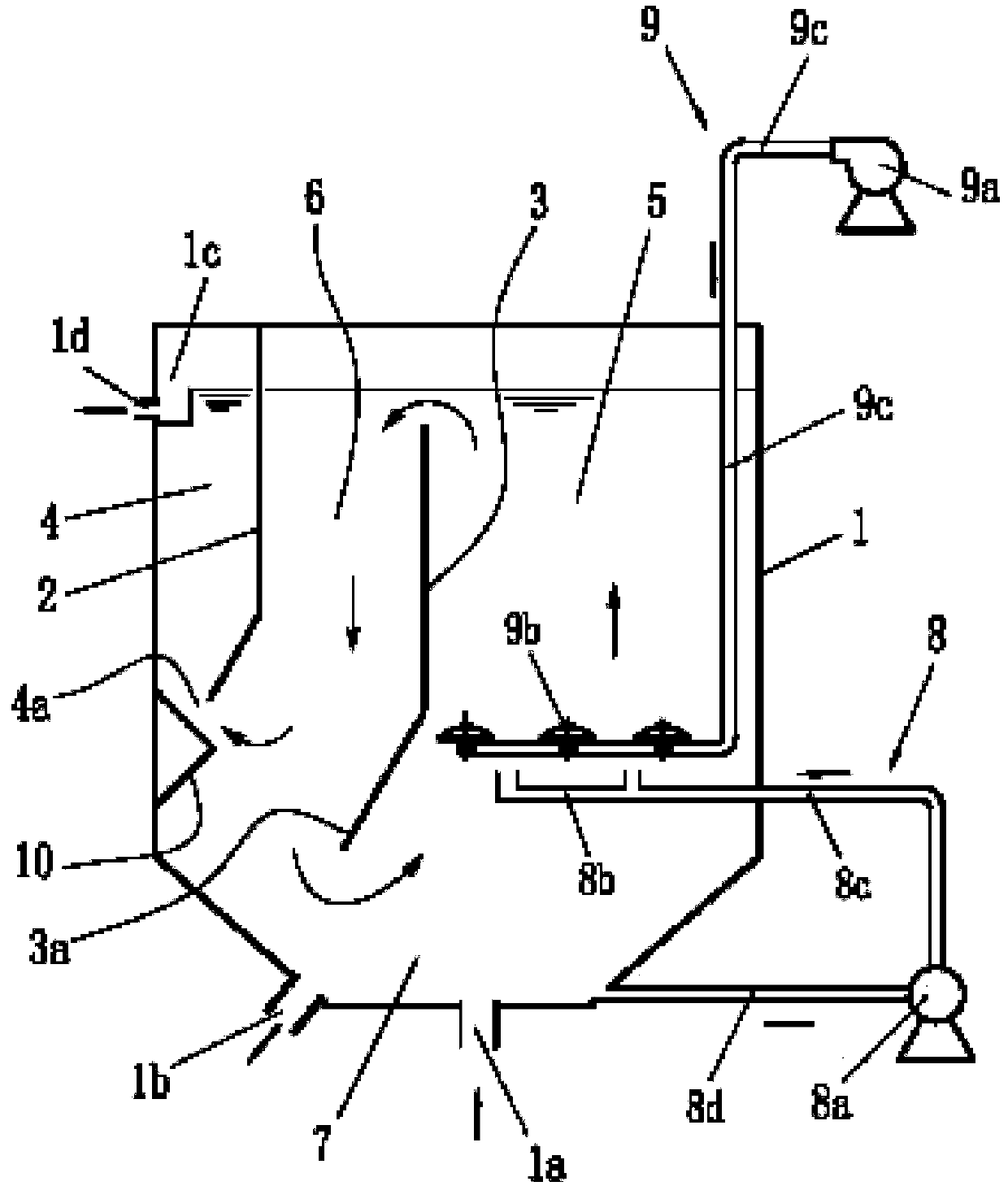
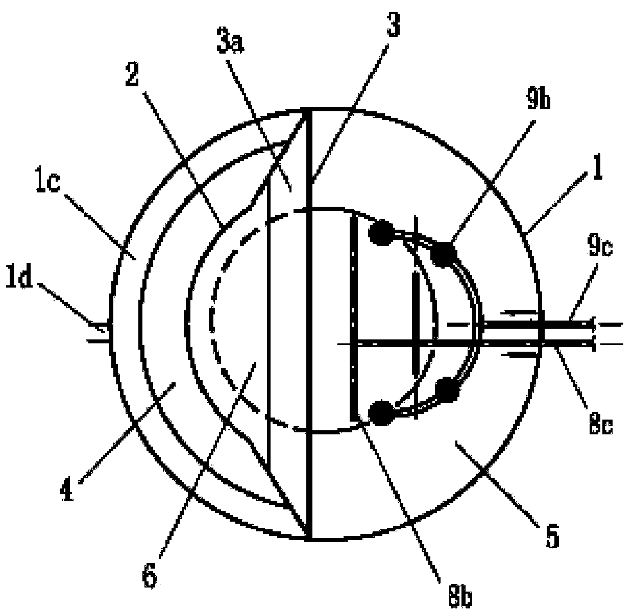
[0031] Referring to the accompanying drawings, the present invention includes a casing 1 of a vertical cylinder; the inner cavity of the casing 1 is provided with an outer vertical plate 2 and an inner vertical plate 3; the outer vertical plate 2 and the casing A mud-water separation zone 4 located in the middle and upper part of the housing is formed between the walls, and the upper part of the mud-water separation zone 4 communicates with the water outlet 1d; the inner vertical plate 3 divides the inner cavity of the housing 1 into two chambers, The chamber on one side of the inner vertical plate 3 is a water flow ascending channel 5, and the other side is a water flow descending channel 6, and the upper and lower ends of the water flow ascending channel 5 communicate with the upper and lower parts of the water flow descending channel 6 respectively, that is, in the shell A water circulation channel is formed in the body 1, and the inlet 4a of the mud-water separation area 4 ...


PUM


Abstract

The invention provides a sewage biological denitrification and dephosphorization device, which comprises a casing (1) of a vertical tube body, wherein an outer vertical plate (2) is positioned insidethe casing and communicates with a water outlet opening (1d) and a sludge-water separation region (4) formed between the casing walls; an inner vertical plate (3) is positioned in the casing; the upper and lower ends of a water flow ascending passage (5) positioned at one side are respectively communicated with the upper and lower parts of a water flow descending passage (6) positioned at the other side; a water flow circulation passage is formed in the casing; an inlet of the sludge-water separation region communicates with the middle and lower part of the water flow descending passage; a sludge gathering region (7) arranged under the inner vertical plate communicates with a water inlet (1a) and a sludge discharging opening (1b) of the bottom wall of the inner cavity of the casing; a sludge water inlet of a sludge pump (8a) arranged in a sludge lifting device (8) communicates with the sludge gathering region; a spraying component (8b) is positioned at the middle lower part of the water flow ascending passage (5); an aerator (9b) arranged in an air supply device (9) is positioned at the middle lower part of the water flow ascending passage (5). The sewage biological denitrificationand dephosphorization device has the characteristics that the treatment effect is improved; the operation is stable.

Description

technical field [0001] The invention relates to the technical field of sewage biological treatment, in particular to an integrated sewage biological nitrogen and phosphorus removal device. Background technique [0002] Sewage biological treatment refers to the use of microbial metabolism to remove organic matter, nitrogen, phosphorus, SS and other pollutants in sewage, so that sewage can be purified. The necessary condition to realize biological denitrification and dephosphorization of sewage is to create an anaerobic, anoxic and aerobic environment. [0003] Publication number CN104150589A and application number 201410421119.6 disclose an "integrated non-gradient activated sludge sewage treatment device". To the cylinder and the inner vertical cylinder, the outer vertical cylinder (the so-called "three-phase separator") is located on the upper part of the inner cavity of the shell, and forms an annular mud-water separation zone with the shell wall. The upper part of the m...

Claims


Application Information

Patent Timeline
IPC IPC(8): C02F3/30C02F101/30
CPCC02F3/301C02F3/302C02F3/308C02F2101/30C02F2203/006C02F2301/04Y02W10/10
Inventor 蒋剑虹尹疆唐清畅罗友元
Owner CHINA MACHINERY INT ENG DESIGN & RES INST
Why Eureka
Try Eureka