
Building glass transportation device facilitating loading

A technology for transportation devices and architectural glass, applied in transportation and packaging, multi-axis trolleys, trolley accessories, etc., can solve problems such as glass damage, lower performance of transportation devices, and high labor intensity, and achieve simple structure and good loading and transportation effects , strong practical effect

Inactive Publication Date: 2018-01-26
ZHENGZHOU SOUQU INFORMATION TECH CO LTD
View PDF0 Cites 19 Cited by
  • Summary
  • Abstract
  • Description
  • Claims
  • Application Information

AI Technical Summary

Problems solved by technology

[0002] The main variety of architectural glass is flat glass, which has the advantages of crystal clear and clean surface, light transmission, sound insulation, heat preservation, wear resistance, climate change resistance, and stable material; it is made of quartz sand, sandstone or quartzite, limestone, feldspar, Dolomite and soda ash are the main raw materials, which are made through crushing, screening, batching, high-temperature melting, forming, annealing, cooling, processing and other processes; at present, they are often carried by manual methods, which not only makes the labor intensity too high, Moreover, it is easy to cause damage to the glass due to collision during the transportation process. Although there are corresponding architectural glass transportation devices at present, they are limited by structural and design constraints, and they cannot be flexibly adjusted according to different sizes of glass. At the same time, the glass is still vulnerable to damage due to hard shocks during the handling process, which greatly reduces the performance of the transport device

Method used

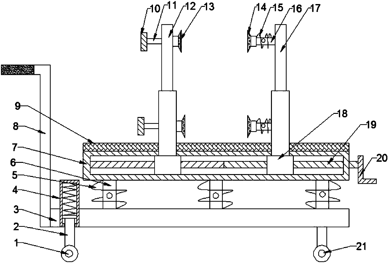

Image

  • Building glass transportation device facilitating loading
  • Building glass transportation device facilitating loading
  • Building glass transportation device facilitating loading

Examples


Embodiment Construction

[0015] The technical solution of this patent will be further described in detail below in conjunction with specific embodiments.

[0016] Embodiments of the present patent are described in detail below, examples of which are shown in the drawings, wherein the same or similar reference numerals designate the same or similar elements or elements having the same or similar functions throughout. The embodiments described below by referring to the figures are exemplary and are only used for explaining the patent, and should not be construed as limiting the patent.

[0017] In the description of this patent, it is to be understood that the terms "center", "upper", "lower", "front", "rear", "left", "right", "vertical", "horizontal", The orientation or positional relationship indicated by "top", "bottom", "inner", "outer", etc. is based on the orientation or positional relationship shown in the drawings, and is only for the convenience of describing this patent and simplifying the des...


PUM


Abstract

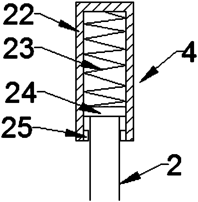
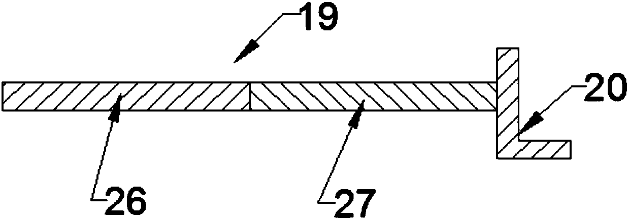
The invention provides a building glass transportation device facilitating loading, and belongs to the technical field of building machinery. A device bottom plate is arranged above a bottom plate through bottom telescopic rods, bottom spiral springs are arranged on the peripheries of the bottom telescopic rods, a driving screw is arranged in an inner cavity of the device bottom plate, a left telescopic rod is arranged on the driving screw through a bottom slider, horizontal telescopic rods are arranged on the upper inner side and the lower inner side a right telescopic rod, spiral springs arearranged on the peripheries of the horizontal telescopic rods, and right suckers are arranged at the left ends of the horizontal telescopic rods. According to the device, rotating directions of a first threaded section and a second threaded section are opposite, so that sliders can approach or keep away from each other, glass is clamped or loosened, a left twisting handle and a left sucker are arranged on the left side and the right side of the left screw, and the building glass can be conveniently and rapidly loaded by tightening the left screw. The device has the advantages of simple structure, high practicability and good loading transportation effect.

Description

technical field [0001] The invention relates to a facility related to construction machinery, in particular to a construction glass transportation device that is convenient for loading. Background technique [0002] The main variety of architectural glass is flat glass, which has the advantages of crystal clear and clean surface, light transmission, sound insulation, heat preservation, wear resistance, climate change resistance, and stable material; it is made of quartz sand, sandstone or quartzite, limestone, feldspar, Dolomite and soda ash are the main raw materials, which are made through crushing, screening, batching, high-temperature melting, forming, annealing, cooling, processing and other processes; at present, they are often carried by manual methods, which not only makes the labor intensity too high, Moreover, it is easy to cause damage to the glass due to collision during the transportation process. Although there are corresponding architectural glass transportati...

Claims


Application Information

Patent Timeline
IPC IPC(8): B62B3/04B62B5/00
Inventor 张秀芝
Owner ZHENGZHOU SOUQU INFORMATION TECH CO LTD
Learn More