Charge pump rectifier and radio frequency energy conversion method
A charge pump and rectifier technology, which is applied in the direction of electrical components, circuit devices, output power conversion devices, etc., can solve the problems of restricting wide application, difficulty in perfect matching of charge pump rectifiers, and large resistance value of nonlinear junction resistance. Power capacity, improving RF-DC power conversion efficiency, and suppressing the effects of odd harmonic components
- Summary
- Abstract
- Description
- Claims
- Application Information
AI Technical Summary
Problems solved by technology
Method used
Image
Examples
Embodiment 1
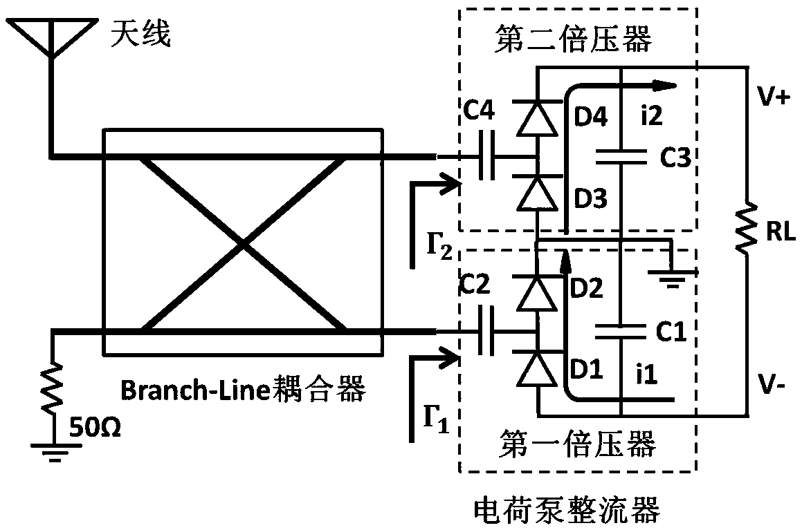
[0032] Such as figure 2 The shown charge pump rectifier includes a Branch-Line coupler connecting the antenna and the charge pump, and the charge pump includes a first voltage doubler and a second voltage doubler with the same structure;
[0033] The first voltage doubler includes a first diode D1 and a second diode D2 connected in series in the same direction, and a first capacitor C1 is connected in parallel at both ends of the first diode D1 and the second diode D2 connected in series, and the first The anode of the diode D1 provides the load negative potential difference V-, the cathode of the first diode D1 is connected to the anode of the second diode D2, the cathode of the second diode D2 is grounded, the first diode D1 and the second The electrode points between the diodes D2 are connected to one end of the second capacitor C2, and the other end of the second capacitor C2 is used as the input end of the first voltage doubler;
[0034] The second voltage doubler inclu...
Embodiment 3
[0055] Such as image 3 The shown charge pump rectifier includes a Branch-Line coupler connecting the antenna and the charge pump, and the charge pump includes a first voltage doubler and a second voltage doubler with the same structure;
[0056] The first voltage doubler includes a first diode D1 and a second diode D2 connected in series in the same direction, and a first capacitor C1 is connected in parallel at both ends of the first diode D1 and the second diode D2 connected in series, and the first The anode of the diode D1 provides the load negative potential difference V-, the cathode of the first diode D1 is connected to the anode of the second diode D2, the cathode of the second diode D2 is grounded, the first diode D1 and the second The electrode points between the diodes D2 are connected to one end of the second capacitor C2, and the other end of the second capacitor C2 is used as the input end of the first voltage doubler;
[0057] The second voltage doubler includ...
Embodiment 2
[0059] In Example 2, by connecting a 50-ohm matching load to the isolated port, the reflected power caused by the mismatch of the charge pump rectifier will all enter the isolated port and be consumed on the 50-ohm resistor, which avoids the above-mentioned reflected electromagnetic wave from affecting the charge pump rectifier. make an impact.
[0060] In order to avoid the above-mentioned emitted electromagnetic waves from being consumed and wasted, the present invention proposes as Figure 4 The circuit configuration shown.
[0061] Example 3
[0062] Such as image 3 The shown charge pump rectifier includes a Branch-Line coupler connecting the antenna and the charge pump, and the charge pump includes a first voltage doubler and a second voltage doubler with the same structure;
[0063] The first voltage doubler includes a first diode D1 and a second diode D2 connected in series in the same direction, and a first capacitor C1 is connected in parallel at both ends of the ...
PUM
 Abstract
Description
Claims
Application Information
 - R&D
- Intellectual Property
- Life Sciences
- Materials
- Tech Scout
- Unparalleled Data Quality
- Higher Quality Content
- 60% Fewer Hallucinations
Browse by: Latest US Patents, China's latest patents, Technical Efficacy Thesaurus, Application Domain, Technology Topic, Popular Technical Reports.
© 2025 PatSnap. All rights reserved.Legal|Privacy policy|Modern Slavery Act Transparency Statement|Sitemap|About US| Contact US: help@patsnap.com


