
Cantilever beam impact pendulnm

An impact pendulum and cantilever beam technology, applied in the direction of using one impact force to test the strength of materials, using repeated force/pulse force to test the strength of materials, etc., can solve the impact test that cannot be done at the same time with multiple energy, heavy operation, single function, etc. problems, to achieve the effect of satisfying the use of multi-energy impact, convenient debugging, and convenient operation

Pending Publication Date: 2018-01-19
湖北省计量测试技术研究院 +1
View PDF6 Cites 1 Cited by
  • Summary
  • Abstract
  • Description
  • Claims
  • Application Information

AI Technical Summary

Problems solved by technology

The existing deficiencies of this cantilever beam impact testing machine mainly show in the following aspects: 1, adopt the pendulum with fixed energy, its function is single, one machine can not do multi-energy impact test at the same time, it needs to replace the whole pendulum Because of the heavy weight of the pendulum, in the process of replacing the pendulum, the workload is heavy and the operation is heavy; 2. The existing pendulum adopts a C-shaped structure, and the part of the pendulum is processed with an inclined plane. The air resistance cannot be minimized; 3. The structure of the C-type pendulum hammer body makes the center of mass of the hammer difficult to fix, and repeated weights are required to ensure that the center of mass is at the striking point, otherwise the hammer shaft will bend during the impact test Phenomenon

Method used


Image

  • Cantilever beam impact pendulnm
  • Cantilever beam impact pendulnm
  • Cantilever beam impact pendulnm

Examples


Embodiment Construction

[0024] Below in conjunction with accompanying drawing and specific embodiment the present invention is described in further detail:

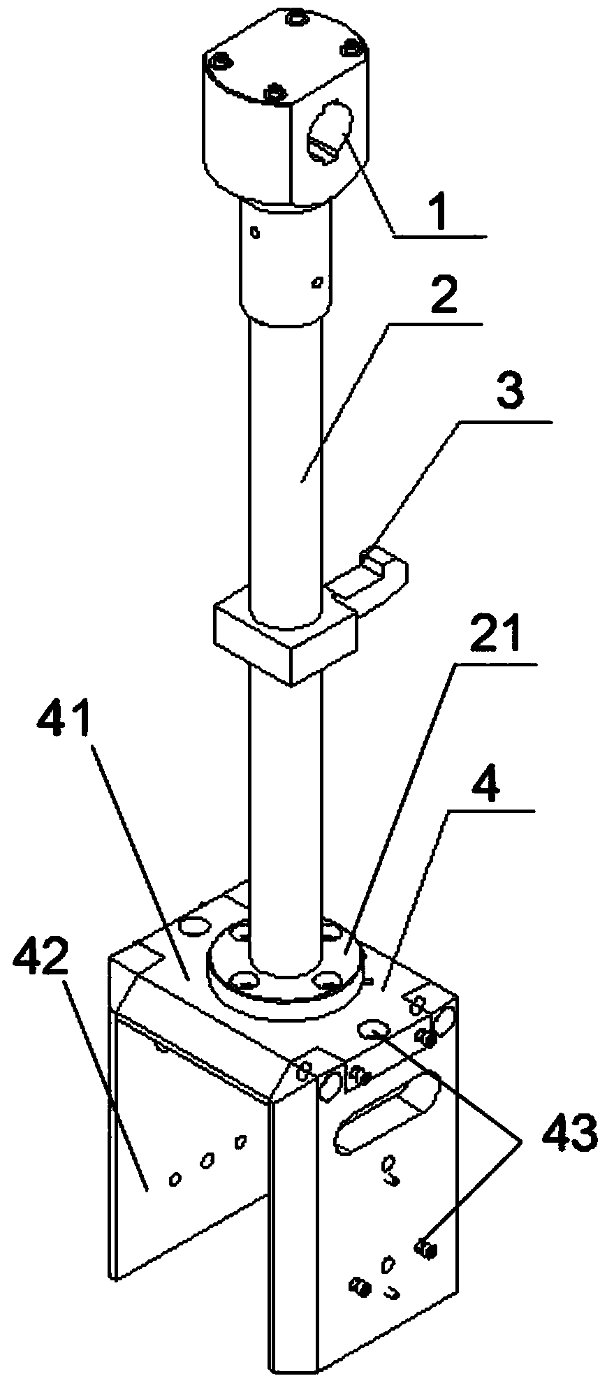
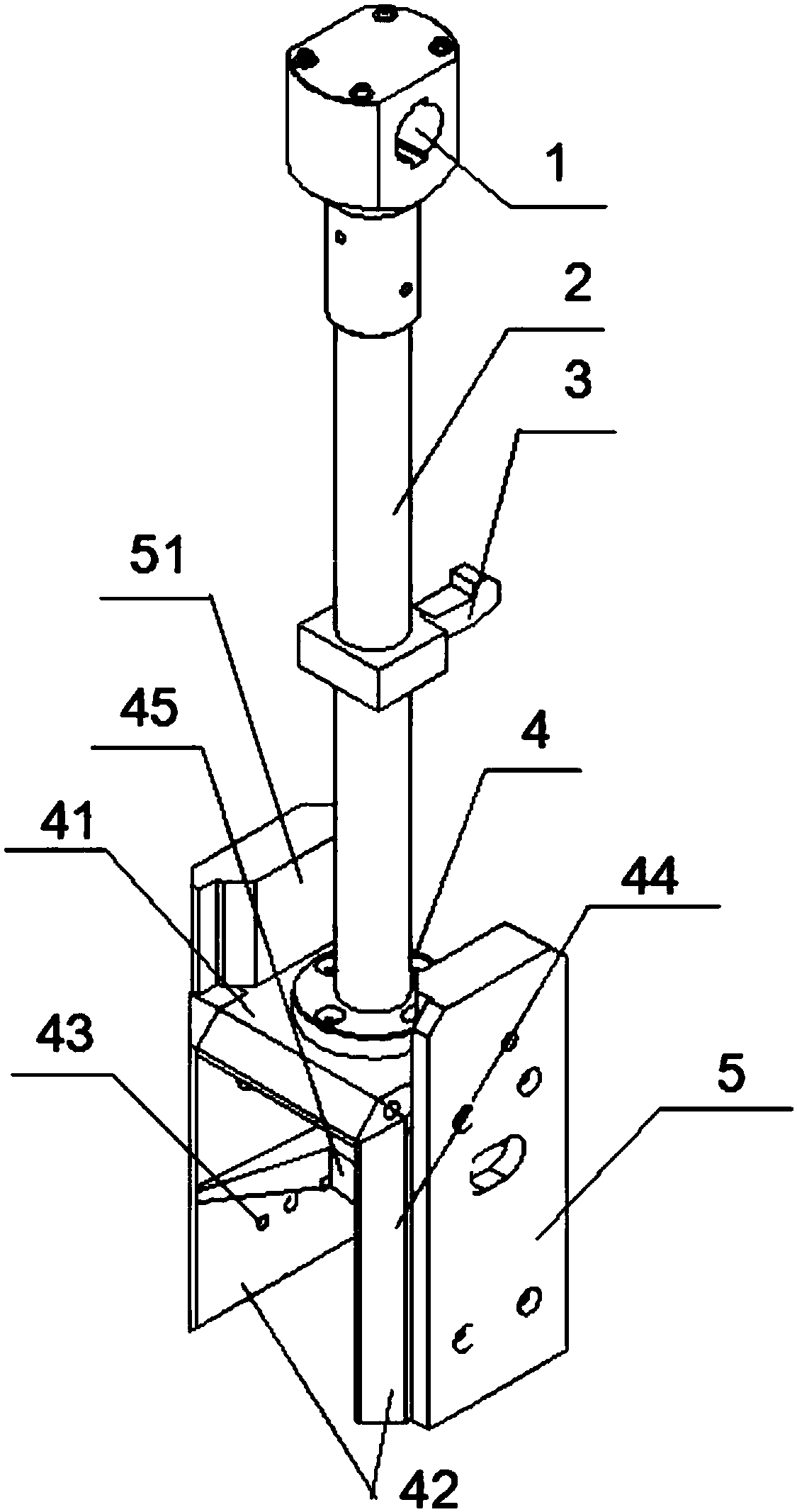
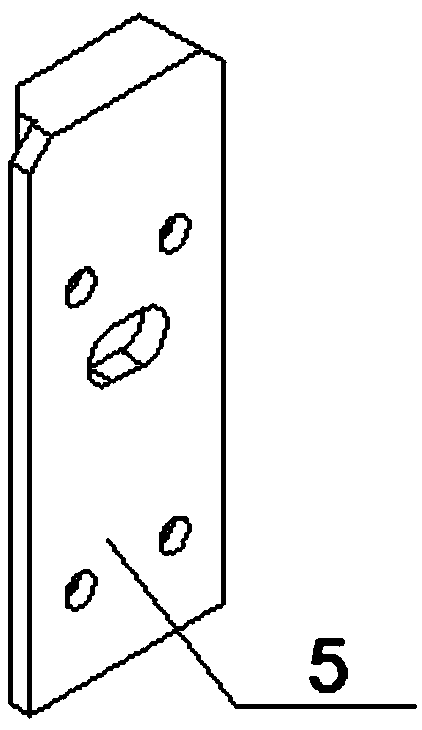
[0025] like figure 1 and figure 2 As shown, the cantilever beam impact pendulum designed in the present invention includes a pendulum suspension mechanism and a pendulum 4, and the pendulum suspension mechanism includes a pendulum 2, a pendulum shaft 1 sleeved on one end of the pendulum and a hook 3 on the pendulum, The pendulum 4 is a U-shaped structure and adopts a U-shaped pendulum arc surface structure 44; the other end of the pendulum 2 is provided with a support seat 21, and the support seat 21 is connected to the center of the pendulum top 41, The top 41 of the pendulum body and the two ends 42 of the pendulum body are all provided with counterweight holes 43 that can be assembled with counterweight weights 5, and the counterweight weights 5 are fitted and connected with the two ends 42 of the pendulum body, and the counterweight weigh...


PUM


Abstract

The invention discloses a cantilever beam impact pendulnm. The cantilever beam impact pendulnm comprises a pendulum body suspension mechanism and a pendulum body, the pendulum body suspension mechanism comprises a swing rod, a pendulum shaft jointed at one end of a swing rod, and a hook on the swing rod, the pendulum body is a U-shaped structure, a supporting seat is arranged at the other end of the swing rod, the supporting seat and a center at top of the pendulum body are connected, counterweight apertures for assembling counterweights are arranged at top of the pendulum body and two ends ofthe pendulum body, the counterweights are connected with two ends of the pendulum body, a support block is arranged at the upper end of the counterweight, and the support block is connected with thecounterweight aperture at the top of the pendulum body. The U-shaped structure of the pendulum body and its arc design can reduce wind resistance to a minimum state, energy loss of a whole machine isreduce to the minimum state, by assembling counterweights with different mass and changing a pre-elevation angle of the pendulum, the impact energy and impact speed are conveniently changed, multi-energy impact usage is satisfied, and the cantilever beam impact pendulnm has the advantages of simple structure and dismounting, convenient debugging, and convenient operation.

Description

technical field [0001] The invention relates to a pendulum impact testing machine, in particular to a cantilever beam impact pendulum. Background technique [0002] The pendulum impact testing machine can be used to measure the impact resistance of metal materials under dynamic load, so as to judge the mechanical properties of materials under dynamic load, and to obtain the impact absorption energy and impact toughness of materials. At present, pendulum impact testing machines are divided into simply supported beam impact testing machines and cantilever beam impact testing machines. The pendulum hammer body structure is similar, such as Figure 7 As shown, a C-shaped impact block is fixed at the lower end of a metal rod, and a V-shaped impact blade is embedded in the C-shaped groove of the impact block. The jaw seats of the two testing machines are different, and are suitable for simply supported beam and cantilever beam respectively. Type, the pre-lift angle is generally 12...

Claims


Application Information

Patent Timeline
Patent Type & Authority Applications(China)
IPC IPC(8): G01N3/30G01N3/34
Inventor 胡翔黄星
Owner 湖北省计量测试技术研究院
Learn More