
Biaxial tensile compression testing device under ultrahigh temperature complex load

A biaxial stretching, complex load technology, applied in measuring devices, using stable tension/pressure testing material strength, instruments, etc. The requirements of water cooling technology, the effect of versatility and compact structure

Pending Publication Date: 2018-01-19
JILIN UNIV
View PDF0 Cites 14 Cited by
  • Summary
  • Abstract
  • Description
  • Claims
  • Application Information

AI Technical Summary

Problems solved by technology

[0004] Compared with foreign research, China still lacks complex mechanical property testing equipment and in-situ observation technology under high temperature conditions. There is still a lot of research to be done on mechanical property testing under high temperature environments, and it is difficult to meet the performance of materials used in ultra-high temperature fields. Evaluation requirements, and under high temperature and complex load environment, fracture failure is one of the most important failure modes. In order to ensure the stability, reliability and durability of heat-resistant composite materials and their products in service, there is an urgent need for a Instruments and equipment for effectively testing the mechanical behavior of materials under complex loads and the coupling damage mechanism of macro-micro-nano in extremely high-temperature environments

Method used


Image

  • Biaxial tensile compression testing device under ultrahigh temperature complex load
  • Biaxial tensile compression testing device under ultrahigh temperature complex load
  • Biaxial tensile compression testing device under ultrahigh temperature complex load

Examples


Embodiment Construction

[0027] The detailed content of the present invention and its specific implementation will be further described below in conjunction with the accompanying drawings.

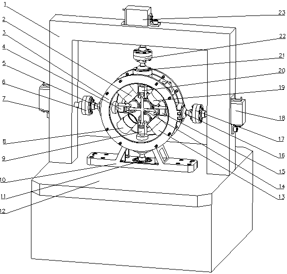
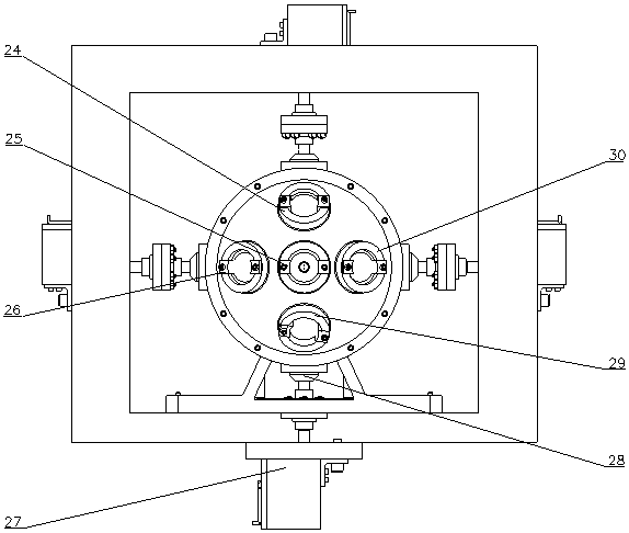
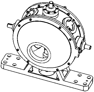
[0028] see Figure 1 to Figure 5 As shown, the ultra-high temperature complex load biaxial tensile compression test device of the present invention includes a biaxial tensile / compressive load driving unit, a bidirectional signal detection and control unit, an ultra-high temperature loading unit, and a clamping unit. The biaxial tensile The compression load drive unit is connected to the gantry column 1 through bolts. The bidirectional signal detection and control unit is composed of tension and pressure sensors I~IV6, 11, 17, and 22, which are rigidly connected with the high-temperature chamber 3 by threads. The ultra-high-temperature loading unit is rigidly fixed in the high-temperature chamber 3, and the clamping unit is clamped on the main axis of the clamp by expansion sleeves I~IV5, 16, 21, and 28. The air-fl...


PUM


Abstract

The invention relates to a biaxial tensile compression testing device under an ultrahigh temperature complex load, and belongs to the technical field of mechanical performance testing of materials. The device comprises a bidirectional tensile / compressive load applying unit, a bidirectional signal detection and control unit, an ultrahigh temperature loading unit, a clamping unit and the like, and is of a vertical gantry structure. Drive, transmission and detection units on each shaft of the device are independent and do not interfere with one another. The bidirectional tensile / compressive loadapplying unit is driven by an electric actuating cylinder, a high-precision direct current servo motor in the bidirectional tensile / compressive load applying unit is used as a driving power source, high speed reduction ratio and torque increase are realized by a miniature multi-stage speed reduction mechanism, in combination with a stress change feedback technology, sufficient loading capacity isensured on the premise of compact structure, and application of the precise load in a quasi-static mode is realized. Real working conditions of material components can be simulated to the maximum extent, and effective means and method are provided for mechanical performance testing of the materials in the high-temperature service state.

Description

technical field [0001] The invention relates to the technical field of material mechanical performance testing, in particular to an ultra-high temperature complex load biaxial tension compression testing device, which integrates driving, loading, detection, and mechanical performance testing of biaxial tension / compression in a force-thermal coupling environment and in-situ The observation is integrated, and it is used for in-situ testing of the micro-mechanical properties of materials under ultra-high temperature and complex load conditions. Background technique [0002] Heat-resistant composite materials have functions such as heat insulation, load bearing, and anti-damage. They are key materials for the design and development of thermal protection systems such as aerospace and weaponry. Heat-resistant composite materials directly determine the advancement and reliability of related systems, weapons, and aircraft. , can not only reduce the weight of the structure, but also g...

Claims


Application Information

Patent Timeline
IPC IPC(8): G01N3/18G01N3/02
Inventor 赵宏伟王岩张建海张世忠谢英杰赵运来徐博达
Owner JILIN UNIV
Learn More