Movable rotary drilling machine for decoration

A drilling machine and rotary motor technology, applied in fixed drilling machines, work accessories, manufacturing tools, etc., can solve the problems of limited workmanship, shortened service cycle, low labor intensity, etc., to save time and manpower, improve work efficiency, The effect of increasing the working range

Inactive Publication Date: 2018-01-19
安徽大富智慧云科技有限公司
View PDF5 Cites 5 Cited by
  • Summary
  • Abstract
  • Description
  • Claims
  • Application Information

AI Technical Summary

Problems solved by technology

[0003] Drilling machine refers to the general name of machinery and equipment that uses tools harder and sharper than the target object to leave cylindrical holes or holes on the target object by means of rotary cutting or rotary extrusion. It plays a very important role in industrial production. important role, but the drilling machine in the prior art is not very convenient to move up, down, left, and right during the overall operation process. Due to the heavy weight of the drilling machine itself, the artificial workmanship is limited and the operation is inconvenient, resulting in low production efficiency.
The existing drilling machine is comfortable to operate and has low labor intensity, but when the motor of the drilling machine is turned on at high speed, because it is movable and perpendicular to the hard ground, the drill rod will be affected by the ground reaction force when it rotates. Shaking makes the connection between it and the motor loose and easy to fall off, which seriously shortens the service life, causes waste of resources, and increases production costs

Method used


Image

  • Movable rotary drilling machine for decoration
  • Movable rotary drilling machine for decoration
  • Movable rotary drilling machine for decoration

Examples


Embodiment Construction

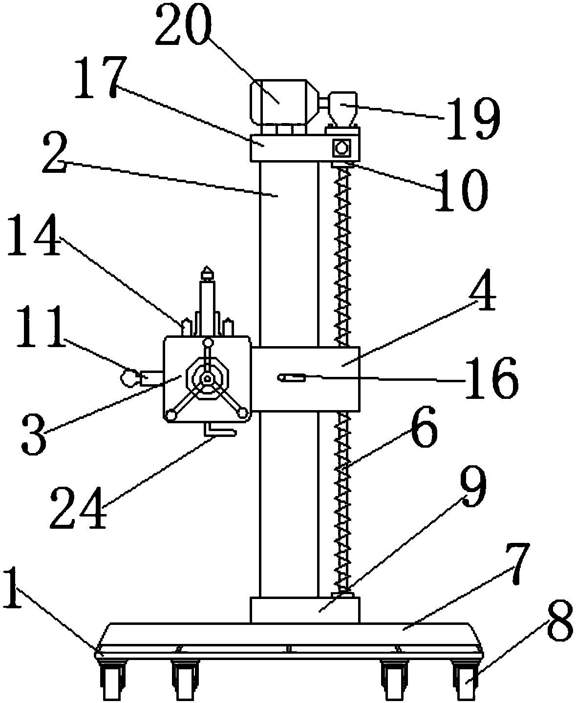
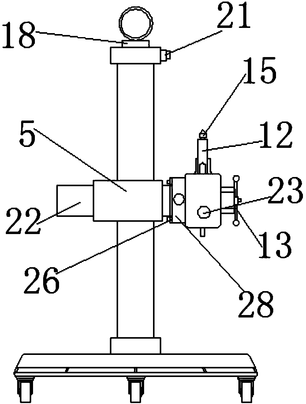
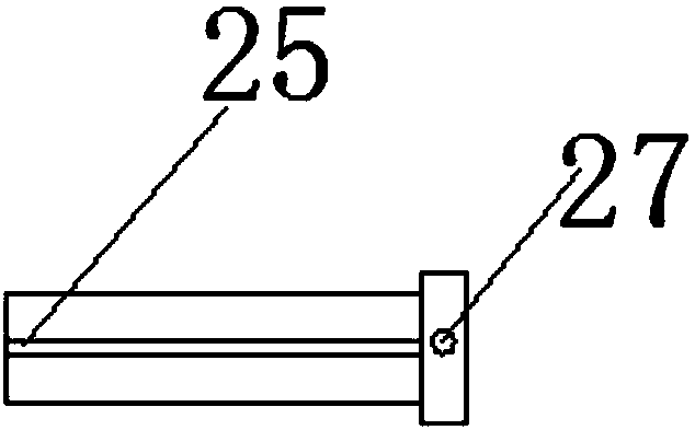
[0016] The following will clearly and completely describe the technical solutions in the embodiments of the present invention with reference to the accompanying drawings in the embodiments of the present invention. Obviously, the described embodiments are only some, not all, embodiments of the present invention. Based on the embodiments of the present invention, all other embodiments obtained by persons of ordinary skill in the art without making creative efforts belong to the protection scope of the present invention.

[0017] In the description of the present invention, it should be noted that the orientation or positional relationship indicated by the terms "vertical", "upper", "lower" and "horizontal" are based on the orientation or positional relationship shown in the drawings, and are only for It is convenient to describe the present invention and simplify the description, but does not indicate or imply that the device or element referred to must have a specific orientati...


PUM


Abstract

The invention discloses a movable rotary drilling machine for decoration. The movable rotary drilling machine comprises a base, a stand column and a main shaft box, wherein a weight increasing bottomplate is arranged at the top end of the base, and the stand column is fixedly connected to the center position of the weight increasing bottom late; a rocker arm is arranged on the stand column; a cantilever is welded to one end of the rocker arm, and a telescopic shaft is connected to an inner hole of the cantilever in an inserted mode; the main shaft box is arranged at the top end of the telescopic shaft, and a connecting base is arranged on the side wall of one side of the main shaft box; and a spring pulling pin is arranged on the outer wall of the connecting base. According to the movablerotary drilling machine, the connecting base and the spring pulling pin are added so that the main shaft box can rotate in four directions, and working range of the drilling machine is expanded; a protruding block of the inner wall of the cantilever is used for being in seamless insertion connection with a groove in the outer wall of the telescopic shaft so that the telescopic shaft can only transversely move in the cantilever, and precision of machining a workpiece by the main shaft box is improved; universal wheels are arranged at the bottom part of the base, so that flexible movement of the drilling machine is realized; and therefore time and labor are effectively saved, and working efficiency is greatly improved.

Description

technical field [0001] The invention relates to the technical field of related mechanical equipment for decoration, in particular to a movable rotary drilling machine for decoration. Background technique [0002] At present, in the process of construction work in the domestic decoration industry, it is necessary to frequently drill holes in the wall or the middle wood. The overall drilling process requires human support, especially in places with high heights, which is even worse for the human body. Control the movement and operation of drilling equipment. More and more construction processes need to use drilling machines, and the whole drilling machine is more and more widely used. [0003] Drilling machine refers to the general name of machinery and equipment that uses tools harder and sharper than the target object to leave cylindrical holes or holes on the target object by means of rotary cutting or rotary extrusion. It plays a very important role in industrial producti...

Claims


Application Information

Patent Timeline
Patent Type & Authority Applications(China)
IPC IPC(8): B28D1/14B28D7/00B27C3/02
Inventor 孙运峰李道春
Owner 安徽大富智慧云科技有限公司
Why Eureka
Try Eureka