
Pitching electric scanning weather radar system and working method thereof

A weather radar and electronic scanning technology, which is applied in the field of pitching electronic scanning weather radar system, can solve the problems of indistinguishable small-scale structures, the temporal and spatial resolution cannot meet the detection of transient fine structures in strong convective weather, etc., and achieves improved temporal and spatial resolution, Fast and efficient monitoring, fast scanning effect

Active Publication Date: 2018-01-16
ANHUI SUN CREATE ELECTRONICS
View PDF5 Cites 3 Cited by
  • Summary
  • Abstract
  • Description
  • Claims
  • Application Information

AI Technical Summary

Problems solved by technology

However, for fast-changing small-to-medium-scale weather processes such as hail, tornado, microburst, wind shear, etc., the temporal and spatial resolution of traditional mechanical scanning radar cannot meet the needs of fine structure detection of strong convective weather transients.
Within 5 minutes, the positions and structures of thunderstorms, hail, tornadoes, and downbursts have changed a lot. It is difficult to distinguish the small-scale structures of these systems with the spatial resolution of existing operational radars. The detection of fine structures in these processes and forecasting urgently need to develop fast-scanning weather radar technology

Method used


Image

  • Pitching electric scanning weather radar system and working method thereof
  • Pitching electric scanning weather radar system and working method thereof
  • Pitching electric scanning weather radar system and working method thereof

Examples


Embodiment Construction

[0047] The following will clearly and completely describe the technical solutions in the embodiments of the present invention with reference to the accompanying drawings in the embodiments of the present invention. Obviously, the described embodiments are only some, not all, embodiments of the present invention. Based on the embodiments of the present invention, all other embodiments obtained by persons of ordinary skill in the art without making creative efforts belong to the protection scope of the present invention.

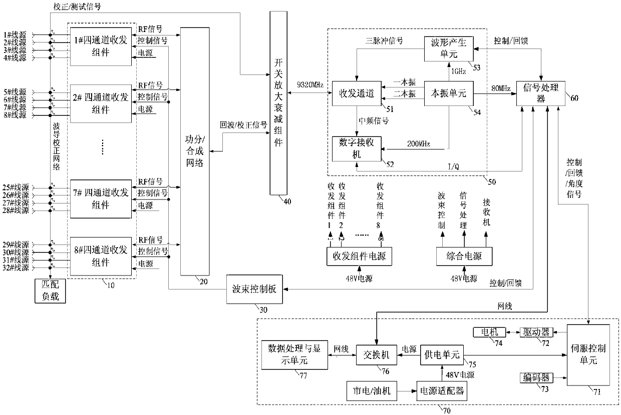
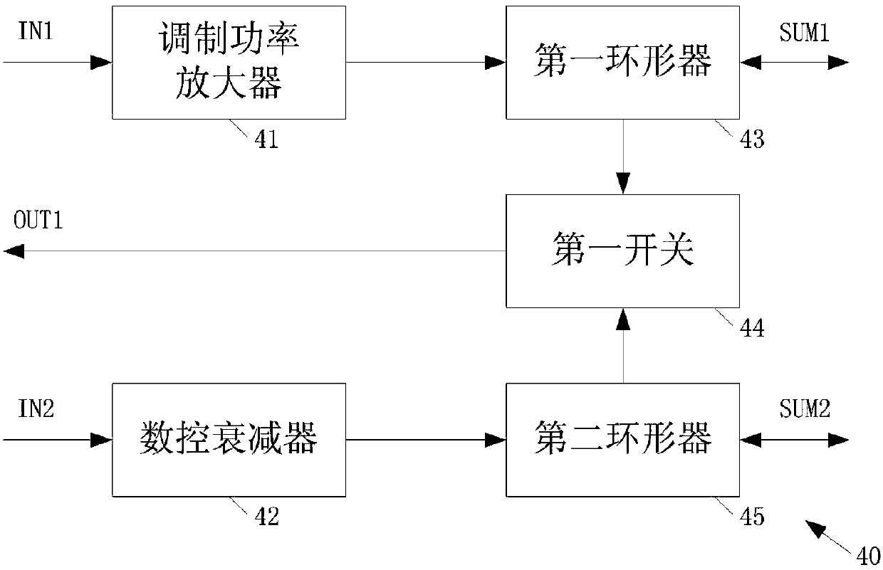
[0048] Such as figure 1 As shown, a pitching electronically swept weather radar system includes a transceiver component module 10, a power division / combination network 20, a beam control board 30, a switch amplification attenuation component 40, a receiver module 50, a signal processor 60, and a turntable module 70. The transceiver component module 10 is used to output the transmission signal after power division / synthesis network 20 to the waveguide source, a...


PUM


Abstract

The invention belongs to the technical field of weather radar system, and particularly relates to a pitching electric scanning weather radar system and a working method thereof. The pitching electricscanning weather radar system includes a transceiver component module, a power dividing / combining network, a beam control board, a switch amplification and attenuation component, a receiver module, asignal processor, and a turntable module. The weather radar system can effectively suppress the crosstalk between pulses and make the splicing points for blind compensation smoother. The efficiency ofthe transceiver component can be maximized, and the repetition frequency can be effectively utilized. The blind area problem of all-solid radar is solved. A high-density scanning area can be monitored quickly and efficiently. The fine structure of a cloud and rain target can be obtained.

Description

technical field [0001] The invention belongs to the technical field of weather radar systems, and in particular relates to an elevation electric sweep weather radar system and a working method thereof. Background technique [0002] Weather radar is a powerful tool for weather detection. The emergence of pulse Doppler weather radar has created a new situation for meteorological work such as the detection of strong storms, the study of cloud and fog physical processes, and artificial weather modification. With the development of society, all walks of life have higher and higher requirements for meteorological detection. [0003] The traditional weather radar system uses long and short pulses, which cannot solve the problem of near-field blind spots. The traditional scanning system uses mechanical scanning methods to change the azimuth and elevation angle of the radar antenna to achieve three-dimensional scanning of the weather process. This scanning method can complete the s...

Claims


Application Information

Patent Timeline
Patent Type & Authority Applications(China)
IPC IPC(8): G01S13/95G01S7/02G01S7/282G01S7/292G01S7/42
CPCY02A90/10
Inventor 程张凡汪旭东郝立勇卞真稳刘琦朱红发王腾飞
Owner ANHUI SUN CREATE ELECTRONICS
Learn More