
A target vacuum diffusion welding system and method

A technology of vacuum diffusion and welding system, applied in welding equipment, non-electric welding equipment, metal processing equipment, etc., can solve the problem of difficult welding of target and flange materials

Active Publication Date: 2019-11-26
KONFOONG MATERIALS INTERNATIONAL CO LTD
View PDF6 Cites 0 Cited by
  • Summary
  • Abstract
  • Description
  • Claims
  • Application Information

AI Technical Summary

Problems solved by technology

[0004] The purpose of the present invention is to provide a target vacuum diffusion welding system and method to solve the technical problem of difficult welding of special-shaped target and flange materials in the prior art

Method used


Image

  • A target vacuum diffusion welding system and method
  • A target vacuum diffusion welding system and method
  • A target vacuum diffusion welding system and method

Examples


Embodiment 1

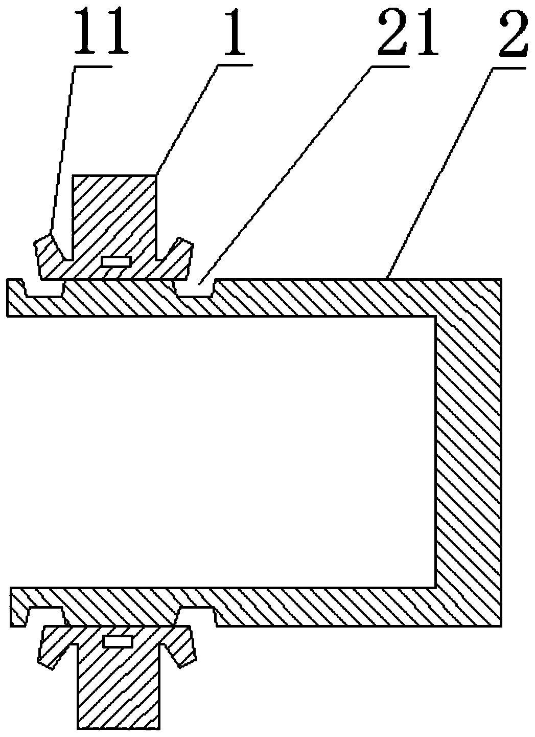
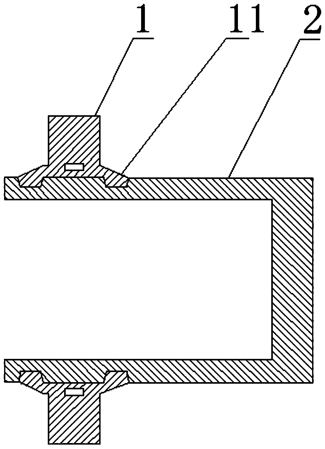
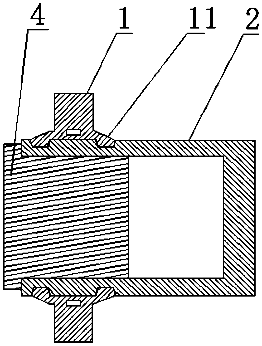
[0033] like Figure 1 to Figure 4 As shown, this embodiment provides a target 2 vacuum diffusion welding system, which includes: a target 2, a flange 1, and a force applying member; the outer peripheral surface of the target 2 is provided with a groove portion 21, and the method The side edge of the flange 1 is provided with a raised portion 11, the flange 1 is assembled on the target 2, and the raised portion 11 is set corresponding to the groove portion 21 to ensure that the raised portion 11 fits in the groove portion 21 when deformed. Of course, the raised portion 11 matches the shape of the groove portion 21 . The biasing member is used to apply stress to the raised portion 11 so that the raised portion 11 fits into the groove portion 21 . The flange 1 is extruded into the target 2 by extrusion on a lathe, and this extrusion assembly method can solve the technical problem of difficult welding of the target 2 with a special shape and the material of the flange 1 .

[00...

Embodiment 2

[0050] like Figure 1 to Figure 4 As shown, the second embodiment also provides a target 2 vacuum diffusion welding method, the target 2 vacuum diffusion welding method is carried out according to the target 2 vacuum diffusion welding system. Of course, the second embodiment includes the technical content disclosed in the first embodiment, and the same technical content as the first embodiment will not be repeated here.

[0051] The target material 2 vacuum diffusion welding method comprises the following steps:

[0052] S1. Assemble the flange 1 on the target 2, and fix the assembled target 2 in the lathe through the inner support fixture; of course, when targeting the pot-shaped target 2, only need to assemble the flange 1 on the pot-shaped For the target material 2, when targeting other shapes of the target material 2, the corresponding operation is sufficient.

[0053] S2. Stress is applied to the raised portion 11 of the flange 1 by means of a force-applying member to d...


PUM


Abstract

The invention relates to the technical field of semiconductor manufacturing and especially relates to a vacuum diffusion welding system for a target material and a method. The vacuum diffusion weldingsystem for the target material at least comprises the target material, a flange and a force applying part, wherein a groove part is arranged on the peripheral surface of the target material; a tilt part is arranged at a lateral edge of the flange; the flange is assembled on the target material; the tilt part is corresponding to the groove part; and the force applying part is used for applying stress to the tilt part so as to embed the tilt part into the groove part. The flange is extruded into the target material in the manner of extruding on a lathe; the extruding assembling method can be adopted for solving the technical problem of welding difficulty of the target material and the flange material in special shape; and furthermore, a columnar part in higher coefficient of thermal expansion is put into the target material for performing vacuum heat treatment in the welding process, so that the diffusion welding is realized.

Description

technical field [0001] The invention relates to the technical field of semiconductor manufacturing, in particular to a target vacuum diffusion welding system and method. Background technique [0002] At present, the target materials for semiconductors are generally high-purity metals, and the backplane materials are generally high-strength and high-hardness alloy metals. Different metal materials have different thermal expansion coefficients, and the degree of metal expansion and contraction during heating and cooling is also different. In the semiconductor industry, there is a kind of target that participates in sputtering. The main part is pot-shaped and the material is high-purity metal. The flange part used to install it on the machine needs to use metal and alloy materials with high hardness. Pure sputtered metal material welded together. Unlike other planar targets, pot-shaped tantalum targets are relatively difficult to weld due to their special structure. If the me...

Claims


Application Information

Patent Timeline
Patent Type & Authority Patents(China)
IPC IPC(8): B23K20/02B23K20/14
Inventor 姚力军潘杰王学泽廖培君
Owner KONFOONG MATERIALS INTERNATIONAL CO LTD
Learn More