
Automobile exhaust treatment device with waste heat using function

A technology for automobile exhaust and treatment devices, which is applied in the direction of exhaust devices, noise reduction devices, and air quality improvement, and can solve problems such as heat loss, environmental pollution, and exhaust gas without purification, so as to achieve sufficient purification treatment and good exhaust gas purification effect , the effect of simple structure

Inactive Publication Date: 2018-01-12
长沙双合盛企业管理有限公司
View PDF4 Cites 3 Cited by
  • Summary
  • Abstract
  • Description
  • Claims
  • Application Information

AI Technical Summary

Problems solved by technology

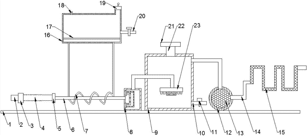
[0002] With the rapid development of the global economy in recent decades, cars have changed from a luxury item to a common means of transportation in people's daily life, but at this stage only a small part of the heat provided by the car fuel is used by the car's power system , the rest of the heat is lost to the environment in the form of heat dissipation and emission, resulting in waste of heat and a certain impact on the atmosphere; the exhaust gas emitted by the car is not purified, and the direct emission also pollutes the environment. In order to solve this problem and reasonably Using automobile exhaust, design an environment-friendly automobile exhaust purification treatment and utilization device to purify automobile exhaust and make use of the exhaust

Method used


Image

  • Automobile exhaust treatment device with waste heat using function
  • Automobile exhaust treatment device with waste heat using function
  • Automobile exhaust treatment device with waste heat using function

Examples


Embodiment Construction

[0017] The technical solution of this patent will be further described in detail below in conjunction with specific embodiments.

[0018] Embodiments of the present patent are described in detail below, examples of which are shown in the drawings, wherein the same or similar reference numerals designate the same or similar elements or elements having the same or similar functions throughout. The embodiments described below by referring to the figures are exemplary and are only used for explaining the patent, and should not be construed as limiting the patent.

[0019] In the description of this patent, it is to be understood that the terms "center", "upper", "lower", "front", "rear", "left", "right", "vertical", "horizontal", The orientation or positional relationship indicated by "top", "bottom", "inner", "outer", etc. is based on the orientation or positional relationship shown in the drawings, and is only for the convenience of describing this patent and simplifying the des...


PUM


Abstract

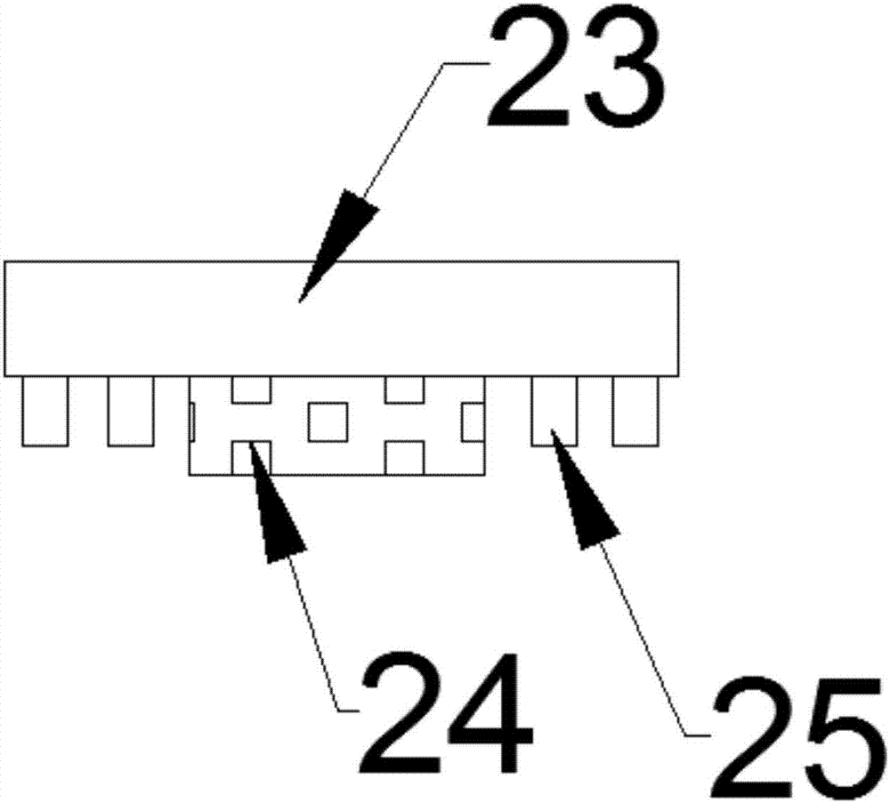
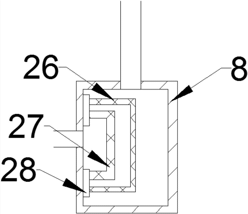
The invention provides an automobile exhaust treatment device with a waste heat using function, and belongs to the technical field of environmental protection purification. The automobile exhaust treatment device comprises a waste heat using device and a purification treatment device; a heat collecting plate is arranged inside a water storage tank; the upper end of a filter tank is connected witha gas outlet plate through an exhaust pipe, and the gas outlet plate is arranged in an inner cavity of a purification container; and the left end of a catalytic converter is connected with the upper portion of the right side of the purification container through an exhaust pipe, and the right end of the catalytic converter is connected with a coiled pipe through an exhaust pipe. According to the automobile exhaust treatment device, a copper pipe is wound around a heat conducting pipe, the two ends of the copper pipe are arranged in openings in the bottom of the water storage tank, and the functions of recycling the waste heat and being used for heating the water storage tank are achieved; a diffuser is arranged on the lower face of the gas outlet plate in a connected manner, the diffuser enables automobile exhaust to be diffused in purification liquid through a plurality of through holes, and the function of sufficient in purification treatment is achieved; and the automobile exhaust treatment device has the beneficial effects of being simple in structure, high in practicability and good in exhaust purification effect.

Description

technical field [0001] The invention relates to an environment-friendly purification facility, in particular to an automobile tail gas treatment device with waste heat utilization. Background technique [0002] With the rapid development of the global economy in recent decades, cars have changed from a luxury item to a common means of transportation in people's daily life, but at this stage only a small part of the heat provided by the car fuel is used by the car's power system , the rest of the heat is lost to the environment in the form of heat dissipation and emission, resulting in waste of heat and a certain impact on the atmosphere; the exhaust gas emitted by the car is not purified, and the direct emission also pollutes the environment. In order to solve this problem and reasonably Using automobile exhaust, an environment-friendly automobile exhaust purification treatment and utilization device is designed to purify automobile exhaust and utilize the exhaust. Content...

Claims


Application Information

Patent Timeline
Patent Type & Authority Applications(China)
IPC IPC(8): F01N5/02F01N13/00F01N3/021F01N3/08F01N3/28
CPCY02A50/20Y02T10/12
Inventor 陆江斌
Owner 长沙双合盛企业管理有限公司
Learn More