Co-rectifier transformer medium voltage type regenerative braking energy feedback device and control method thereof
A rectifier transformer and regenerative braking technology, which is applied in electric braking system, output power conversion device, AC power input conversion to DC power output, etc., can solve the problem of reducing the efficiency of system feedback energy, complex system circuits, and Complicated problems, to achieve the effect of eliminating circulating current, increasing feedback capacity, and reducing current harmonic content
- Summary
- Abstract
- Description
- Claims
- Application Information
AI Technical Summary
Problems solved by technology
Method used
Image
Examples
Embodiment 1
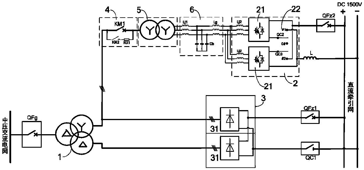
[0039] like figure 1 As shown, the co-rectifier transformer medium-voltage regenerative braking energy feedback device of this embodiment includes a rectifier transformer 1, an energy feedback unit 2 and a rectifier unit 3, and the energy feedback unit 2 and the rectifier unit 3 are arranged in parallel on the valve side of the rectifier transformer 1 Between the winding and the DC traction network, the grid-side winding of the rectifier transformer 1 is connected to the medium-voltage AC grid, and the grid-connected switch 4 and the isolation transformer 5 (isolated Transformer 5 matches the valve-side winding phase of rectifier transformer 1, that is, it is consistent with the valve-side winding phase of rectifier transformer 1), energy feed unit 2 includes two inverters 21, and the AC sides of the two inverters 21 are connected in parallel , the DC sides of the two inverters 21 are provided with a single-pole double-ended isolating switch group 22 for connecting the two inv...
Embodiment 2
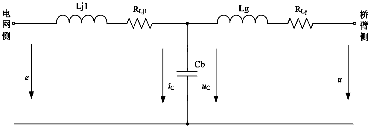
[0065] like image 3 As shown, the co-rectification transformer medium-voltage regenerative braking energy feedback device of this embodiment is basically the same as that of Embodiment 1, and the difference is that in Embodiment 1, the three first current-sharing reactors Lj1 are separately set, which will reduce the isolation The volume of the transformer 5, but will increase the volume of the converter cabinet where the inverter 21 is located; Figure 7 As shown, in this embodiment, three first current-sharing reactors Lj1 are integrated and arranged in the isolation transformer 5 (not shown in the figure), so that part of the reactors in the LCL filter 6 are integrated in the isolation transformer 5 , which reduces the volume and cost of a reactor, and reduces the occupied area, but the volume of the isolation transformer 5 will increase relatively.
PUM
 Abstract
Description
Claims
Application Information
 - R&D Engineer
- R&D Manager
- IP Professional
- Industry Leading Data Capabilities
- Powerful AI technology
- Patent DNA Extraction
Browse by: Latest US Patents, China's latest patents, Technical Efficacy Thesaurus, Application Domain, Technology Topic, Popular Technical Reports.
© 2024 PatSnap. All rights reserved.Legal|Privacy policy|Modern Slavery Act Transparency Statement|Sitemap|About US| Contact US: help@patsnap.com


