
Method for fast calibrating transmitting frequency of radar

A technology of transmitting frequency and frequency, applied in the field of radar rapid correction of transmitting frequency, can solve the problems of reduced ranging accuracy, long calibration time, and increased error, and achieve the effect of ensuring timeliness and ensuring radar ranging accuracy.

Active Publication Date: 2018-01-09
纵目科技(厦门)有限公司
View PDF8 Cites 4 Cited by
  • Summary
  • Abstract
  • Description
  • Claims
  • Application Information

AI Technical Summary

Problems solved by technology

[0004] In theory, the refresh frequency of the radar depends on the listening time set by the radar itself, that is, the time of one frame of the radar. However, in practical applications, the transmission frequency of the radar will be affected by the change of the external temperature, resulting in a decrease in the accuracy of the radar itself. , the error increases; in this field, multi-frequency calibration is usually used to control the radar transmission frequency; the actual refresh frequency time of the radar is also added with the calibration time of the transmission frequency on the basis of the monitoring time, and the multi-frequency calibration method requires The long calibration time indirectly reduces the refresh frequency of the radar. It is intuitively reflected that the multi-frequency calibration method is difficult to improve the refresh frequency of the radar and the accuracy of the radar ranging at the same time; therefore, how to reduce the frequency calibration time and improve the timeliness of system alarms Sex is something that needs to be addressed now

Method used


Image

  • Method for fast calibrating transmitting frequency of radar

Examples


Embodiment Construction

[0019] In order to make the purpose, technical solutions and advantages of the embodiments of the present invention clearer, the technical solutions in the embodiments of the present invention will be clearly and completely described below in conjunction with the accompanying drawings in the embodiments of the present invention. Obviously, the described embodiments It is some embodiments of the present invention, but not all of them. The implementation manners in the present invention and all other implementation manners obtained by persons of ordinary skill in the art without making creative efforts belong to the scope of protection of the present invention. Accordingly, the following detailed description of the embodiments of the invention provided in the accompanying drawings is not intended to limit the scope of the claimed invention, but merely represents selected embodiments of the invention. The implementation manners in the present invention and all other implementatio...


PUM


Abstract

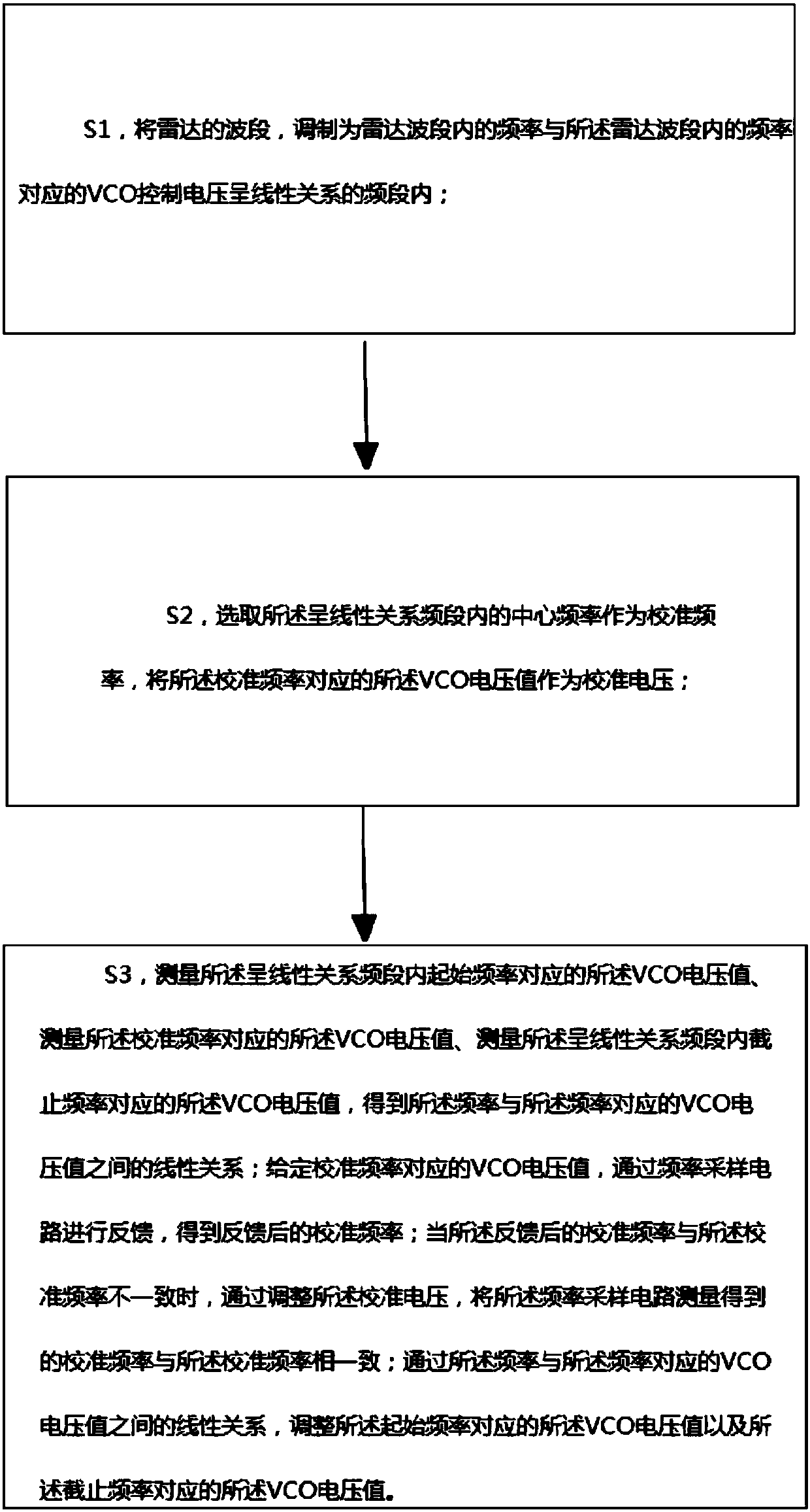
The present invention provides a method for fast calibrating the transmitting frequency of a radar. The method comprises the following steps that: S1, the wave band of the radar is modulated so as tobe a frequency band in which the frequencies of the radar under the wave band are in linear relationships with VCO control voltages corresponding to the frequencies of the radar; S2, a center frequency in the frequency band in which the frequencies are in linear relationships with the VCO control voltages is selected as a calibration frequency, a VCO voltage value corresponding to the calibrationfrequency is adopted as a calibration voltage; and S3, a VCO voltage value corresponding to an initial frequency in the frequency band in which the frequencies are in linear relationships with the VCOcontrol voltages, a VCO voltage value corresponding to the calibration frequency, and a VCO voltage value corresponding to a cut-off frequency in the frequency band in which the frequencies are in linear relationships with the VCO control voltages are measured, so that linear relationships between the frequencies and the VCO voltage values are obtained. The VCO voltage value corresponding to thecalibration frequency is given; feedback is performed through a frequency sampling circuit, so that a feedback-post calibration frequency is obtained; and when the feedback-post calibration frequencyis inconsistent with the calibration frequency, the calibration voltage is adjusted, so that the calibration frequency measured by the frequency sampling circuit is made to be consistent with the calibration frequency.

Description

technical field [0001] The invention relates to the technical field of radar calibration, in particular to a method for quickly correcting the transmission frequency of a radar. Background technique [0002] Radar, that is, "radio detection and ranging", uses radio methods to find targets and determine their spatial positions; [0003] In practical applications, the faster the refresh rate of the radar, the higher the refresh rate of the distance between the vehicle and the obstacle equipped with the radar. Collision; [0004] In theory, the refresh frequency of the radar depends on the listening time set by the radar itself, that is, the time of one frame of the radar. However, in practical applications, the transmission frequency of the radar will be affected by the change of the external temperature, resulting in a decrease in the accuracy of the radar itself. , the error increases; in this field, multi-frequency calibration is usually used to control the radar transmis...

Claims


Application Information

Patent Timeline
IPC IPC(8): G01S7/40
Inventor 陈子凯唐锐苏晓坚
Owner 纵目科技(厦门)有限公司
Learn More