
Optical fiber F-P cavity pressure sensor temperature compensation method

A pressure sensor and temperature compensation technology, which is applied in the direction of fluid pressure measurement, measurement of fluid pressure, instruments, etc. using optical methods, can solve the problems of temperature influence of optical fiber F-P cavity pressure sensor, and achieve the effect of improving measurement accuracy

Active Publication Date: 2018-01-09
NORTHWESTERN POLYTECHNICAL UNIV
View PDF5 Cites 6 Cited by
  • Summary
  • Abstract
  • Description
  • Claims
  • Application Information

AI Technical Summary

Problems solved by technology

[0004] In order to solve the problem that the existing optical fiber F-P cavity pressure sensor is affected by temperature, the present invention aims to provide a simple and efficient temperature compensation method for this type of sensor without changing the original structure of the sensor, without adding additional sensing components, Make it possible to accurately measure pressure in different temperature environments

Method used


Image

  • Optical fiber F-P cavity pressure sensor temperature compensation method
  • Optical fiber F-P cavity pressure sensor temperature compensation method
  • Optical fiber F-P cavity pressure sensor temperature compensation method

Examples


Embodiment

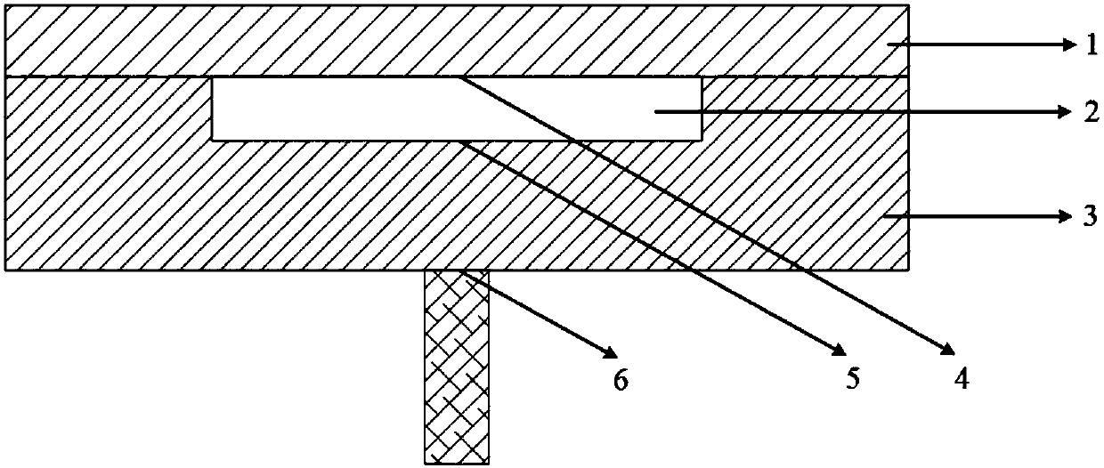
[0037] A method for temperature compensation of a silicon glass-based F-P cavity pressure sensor. First, the specific parameters of the silicon glass-based F-P cavity pressure sensor are briefly explained. The length of the F-P cavity is 21 μm, the thickness of the circular sensitive diaphragm is 46 μm, the diameter of the diaphragm and the F-P cavity is 1300 μm, and the thickness of the lower glass plate is 500 μm.

[0038] step one:

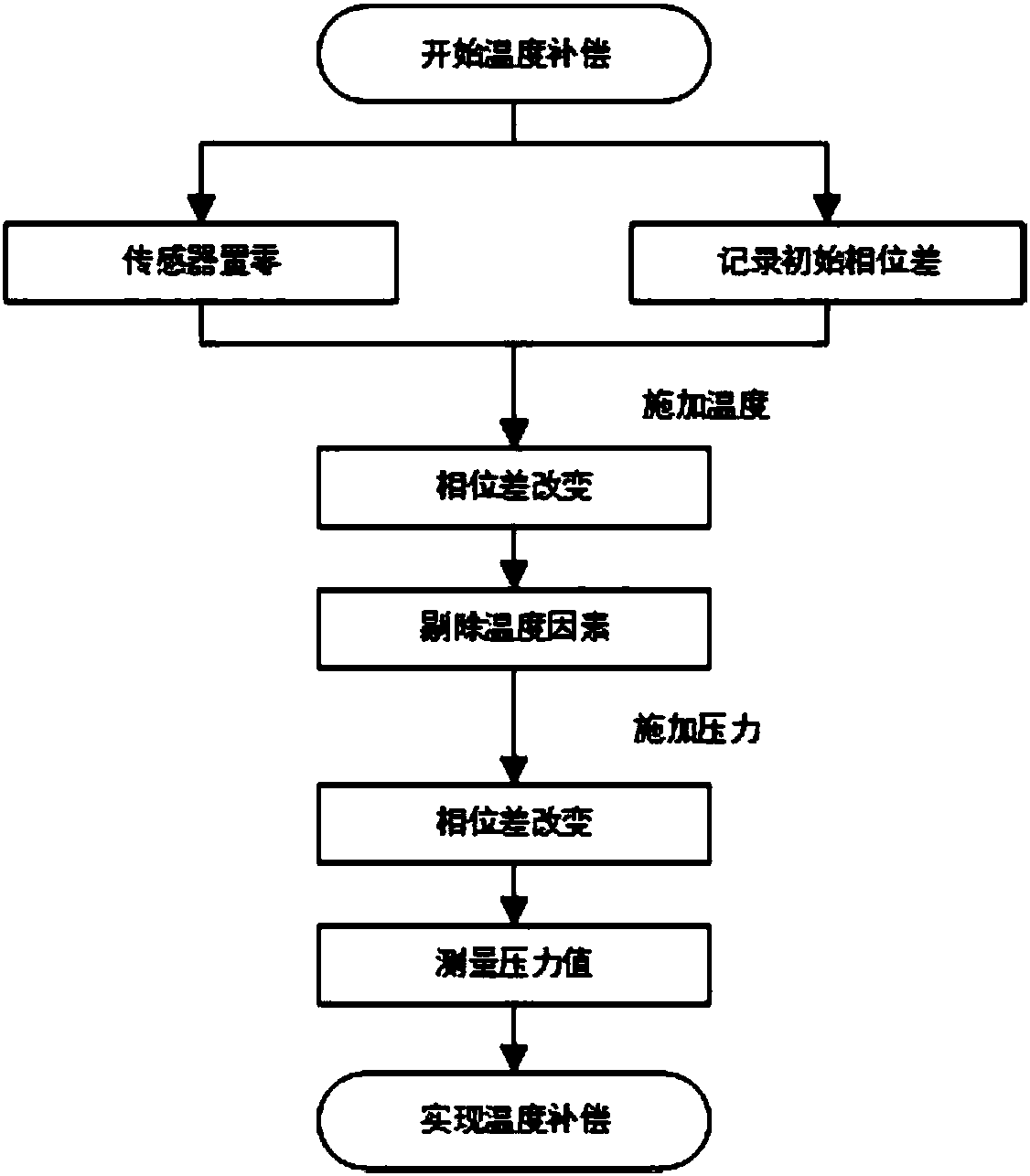
[0039] The sensor is zeroed and the initial phase difference is recorded. For the convenience of calculation, the initial room temperature is set at 25°C, and λ 0 = Light in the infrared band with a wavelength of 1500nm. θ takes normal incidence, that is, θ=90°, cosθ=1. The middle of the F-P cavity is air medium, its refractive index n=1, and the refractive index of glass n′=1.5, then the phase difference δ of the F-P cavity layer can be calculated by using the above formulas 1 and 2 0 =56π,δ 1 =2000π.

[0040] Step two:

[0041] Relevan...


PUM

PropertyMeasurementUnit
thicknessaaaaaaaaaa
diameteraaaaaaaaaa
thicknessaaaaaaaaaa

Abstract

The invention belongs to the technical field of micro-electro-mechanical system (MEMS) high-temperature pressure sensing, and relates to an optical fiber F-P (Fabry-Perot interferometer) cavity pressure sensor temperature compensation method. For the problem of temperature drift which causes measurement error of an optical fiber F-P cavity pressure sensor, the method utilizes the unutilized structure of the sensor itself and signals existing in the measurement process but filtered out as interference signals, and eliminates temperature factors in the measurement process through a subsequent temperature compensation algorithm; and such temperature compensation algorithm can achieve purposes of reducing structure complexity of the sensor and achieving temperature compensation through a simplest and most efficient method.

Description

(1) Technical field [0001] The invention belongs to the technical field of micro-electromechanical systems (MEMS) high-temperature pressure sensing, and relates to a temperature compensation method for an optical fiber F-P cavity (Fabry-Perot interferometer) type pressure sensor. (2) Background technology [0002] The output signal of the high temperature pressure sensor will change with the temperature of the measured medium (gas or liquid), that is, zero temperature drift and sensitivity temperature drift will occur, which are the main factors causing pressure measurement errors in high temperature environments. Therefore, after the pressure sensor is manufactured, it is necessary to measure the change of the output signal with the temperature of the measured medium (gas or liquid), and compensate the zero temperature drift and sensitivity temperature drift in an appropriate way. [0003] The theoretical design temperature of the existing optical fiber F-P cavity pressure ...

Claims


Application Information

Patent Timeline
Patent Type & Authority Applications(China)
IPC IPC(8): G01L11/02G01L19/04
Inventor 苑伟政马志波郭雪涛张晗
Owner NORTHWESTERN POLYTECHNICAL UNIV
Learn More