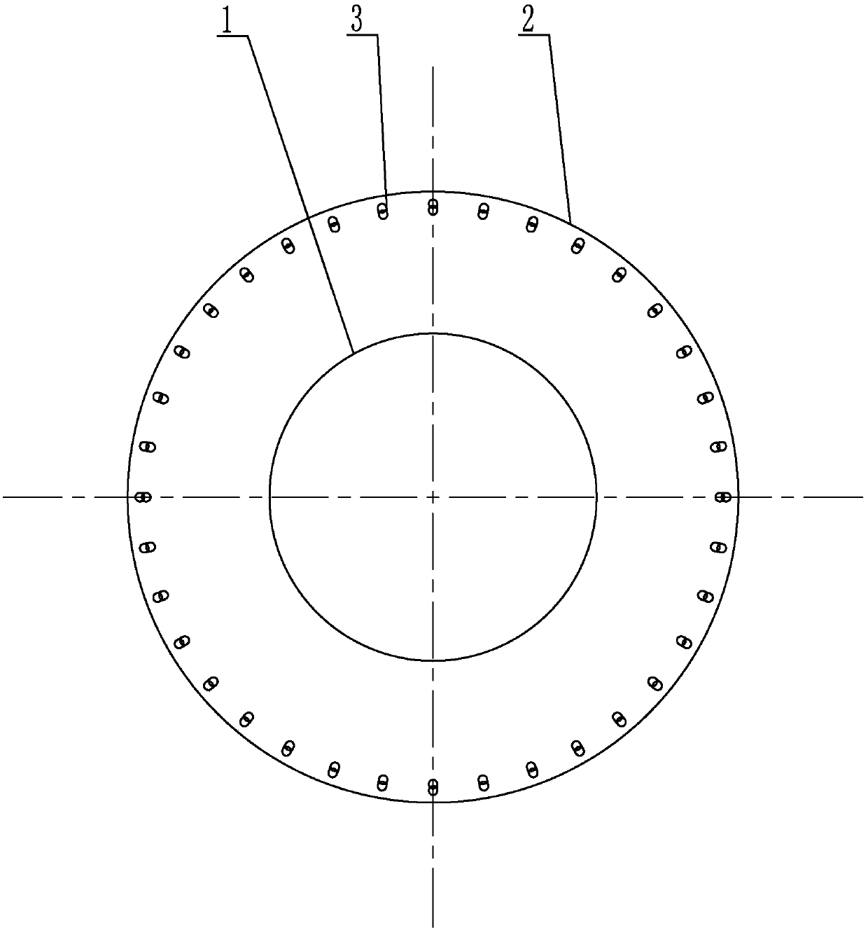
Preignition chamber with surrounding air suitable for rotational flow pulverized coal burner
A pulverized coal burner and pre-combustion chamber technology, which is applied in the direction of burning powder fuel burners, burners, and the combustion of block fuel and powder fuel, and can solve the problem of easy ash accumulation and slagging in the pre-combustion chamber problems, to avoid high-temperature flue gas erosion, protect the pre-combustion chamber, and prolong the service life
- Summary
- Abstract
- Description
- Claims
- Application Information
AI Technical Summary
Problems solved by technology
Method used
Image
Examples
specific Embodiment approach 1
[0017] Specific implementation mode one: combine figure 1 and figure 2 Describe this embodiment, a pre-combustion chamber with peripheral wind suitable for a swirl pulverized coal burner described in this embodiment includes a pre-combustion chamber 2 and a plurality of peripheral air nozzles 3, and the swirl pulverized coal burner 1 is arranged on the pre-combustion chamber In the middle of the bottom of the combustion chamber 2, the bottom of the pre-combustion chamber 2 is evenly distributed with a plurality of peripheral wind nozzles 3 along the circumferential direction, the peripheral wind nozzles 3 are inserted on the bottom surface of the pre-combustion chamber 2, and the inner side of the peripheral wind nozzle 3 is close to the pre-combustion chamber. On the inner cylinder wall of the combustion chamber 2, gas is transported in the peripheral wind nozzle 3 .
[0018] The air required for combustion passes through the swirl pulverized coal burner 1 and forms a swirl...
specific Embodiment approach 2
[0019] Specific implementation mode two: combination figure 1 and figure 2 Describe this embodiment, the inner diameter of the peripheral air nozzle 3 in this embodiment is 10 mm to 30 mm, and the distance between the center line of the inner end surface of the peripheral air nozzle 3 and the inner cylinder wall of the pre-combustion chamber 2 is 10 mm to 30 mm. Other compositions and connection methods are the same as those in Embodiment 1.
[0020] This design guarantees the gas flow velocity of the peripheral wind nozzle 3, i.e. the wind speed, and on the other hand ensures that the inner side of the peripheral wind nozzle 3 is close to the inner cylinder wall of the pre-combustion chamber 2.
specific Embodiment approach 3
[0021] Specific implementation mode three: combination figure 1 and figure 2 To describe this embodiment, an included angle α is set between the axial direction of the peripheral air nozzle 3 and the inner cylinder wall of the pre-chamber 2 in this embodiment. Other compositions and connection modes are the same as those in Embodiment 1 or 2.
[0022] The angle α between the axial direction of the peripheral wind nozzle 3 and the inner cylinder wall of the pre-chamber 2 can be adjusted according to needs, so as to ensure that the air flow is sprayed into the inner cylinder wall of the pre-chamber 2, and on the inner cylinder wall of the pre-chamber 2 A layer of "air film" is formed to prevent coal powder and ash from depositing on the wall of the pre-combustion chamber 2, and achieve the purpose of preventing powder accumulation and slagging in the pre-combustion chamber.
PUM
 Abstract
Description
Claims
Application Information
 - R&D
- Intellectual Property
- Life Sciences
- Materials
- Tech Scout
- Unparalleled Data Quality
- Higher Quality Content
- 60% Fewer Hallucinations
Browse by: Latest US Patents, China's latest patents, Technical Efficacy Thesaurus, Application Domain, Technology Topic, Popular Technical Reports.
© 2025 PatSnap. All rights reserved.Legal|Privacy policy|Modern Slavery Act Transparency Statement|Sitemap|About US| Contact US: help@patsnap.com


