
Preparation method of Schottky diode and Schottky diode

A Schottky diode, N-type technology, applied in semiconductor/solid-state device manufacturing, electrical components, circuits, etc., can solve problems such as large reverse leakage current

Inactive Publication Date: 2018-01-05
PEKING UNIV FOUNDER GRP CO LTD +1
View PDF3 Cites 0 Cited by
  • Summary
  • Abstract
  • Description
  • Claims
  • Application Information

AI Technical Summary

Problems solved by technology

[0002] In the related art, the structure of the trench Schottky diode is as follows figure 1 As shown, it specifically includes: N-type substrate 102, N-type epitaxial layer 104, dielectric layer trench 106, polysilicon 108 and metal electrode 110 filled in the dielectric layer trench. On the one hand, the electric field intensity is changed by the effect of electric field depletion Distribution, the maximum value of the electric field intensity is transferred from the Schottky junction position to the bottom 112 of the dielectric layer trench. On the other hand, the trench Schottky diode can also reduce the maximum value of the electric field intensity in the active region, thereby improving Reverse breakdown voltage, but the Schottky barrier effect is still obvious, and the reverse leakage current of the device is large

Method used


Image

  • Preparation method of Schottky diode and Schottky diode
  • Preparation method of Schottky diode and Schottky diode
  • Preparation method of Schottky diode and Schottky diode

Examples


Embodiment Construction

[0029] In order to understand the purpose, features and advantages of the present invention more clearly, the present invention will be further described in detail below in conjunction with the accompanying drawings and specific embodiments. It should be noted that, in the case of no conflict, the embodiments of the present application and the features in the embodiments can be combined with each other.

[0030] In the following description, many specific details are set forth in order to fully understand the present invention. However, the present invention can also be implemented by a third party different from the third party described here. Therefore, the protection scope of the present invention is not limited by the following disclosure. limitations of specific examples.

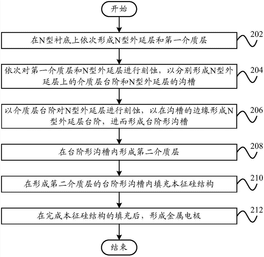
[0031] Combine below Figure 2 to Figure 11 The preparation scheme of the Schottky diode and the diode according to the embodiment of the present invention are described in detail.

[0032] figure ...


PUM


Abstract

The invention provides a preparation method of a Schottky diode and a Schottky diode. The preparation method comprises the steps of sequentially forming an N type epitaxial layer and a first dielectric layer on an N type substrate; performing etching on the first dielectric layer and the N type epitaxial layer in sequence to respectively form a dielectric layer step on the N type epitaxial layer and a trench of the N type epitaxial layer; etching the N type epitaxial layer by taking the dielectric layer step as a mask so as to form an N type epitaxial layer step at the edge of the trench, andthus forming a stepped trench; forming a second dielectric layer in the stepped trench; filling an intrinsic silicon structure in the stepped trench in which the second dielectric layer is formed; andforming a metal electrode at the completion of filling of the intrinsic silicon structure. According to the technical scheme of the invention, the electric field intensity inside the device in the conduction process is reduced, the maximum electric field intensity value is significantly reduced in particular, and thus the Schottky barrier lowering effect of the device is effectively reduced, so that the reverse leakage current is reduced.

Description

technical field [0001] The invention relates to the technical field of semiconductor manufacturing, in particular to a method for preparing a Schottky diode and a Schottky diode. Background technique [0002] In the related art, the structure of the trench Schottky diode is as follows figure 1 As shown, it specifically includes: N-type substrate 102, N-type epitaxial layer 104, dielectric layer trench 106, polysilicon 108 and metal electrode 110 filled in the dielectric layer trench. On the one hand, the electric field intensity is changed by the effect of electric field depletion Distribution, the maximum value of the electric field intensity is transferred from the Schottky junction position to the bottom 112 of the dielectric layer trench. On the other hand, the trench Schottky diode can also reduce the maximum value of the electric field intensity in the active region, thereby improving Reverse breakdown voltage, but the Schottky barrier effect is still obvious, and the...

Claims


Application Information

Patent Timeline
IPC IPC(8): H01L21/329H01L29/872
Inventor 李理赵圣哲马万里姜春亮
Owner PEKING UNIV FOUNDER GRP CO LTD
Learn More