Computer-implemented method of calibrating a camera

A realization method, computer technology, applied to computer components, computing, TV system components, etc., can solve problems such as pattern movement, achieve the effects of improving quality, reliable calibration results, and accelerating the calibration process

Active Publication Date: 2018-01-05
DASSAULT SYSTEMES
View PDF4 Cites 3 Cited by
  • Summary
  • Abstract
  • Description
  • Claims
  • Application Information

AI Technical Summary

Problems solved by technology

A person trying to perform two tasks at the same time may end up accidentally shifting the pattern when image acquisition is triggered

Method used


Image

  • Computer-implemented method of calibrating a camera
  • Computer-implemented method of calibrating a camera
  • Computer-implemented method of calibrating a camera

Examples


Embodiment Construction

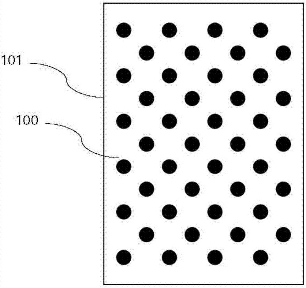
[0053] figure 1 A calibration pattern 100 formed by a regular arrangement of black discs on a white background is shown. Other patterns can be used to implement the invention, such as a checkerboard or grid, but this pattern proves to be particularly advantageous as it provides the best accuracy with the lowest number of poses, see A. Datta et al. "Accurate Camera Calibration using Iterative Refinement of Control Points” IEEE 12th International Conference on Computer Vision Workshops (ICCV Workshops), 2009. The pattern is carried by a physical support 101, which may be, for example, a rigid cardboard panel. Three-dimensional (ie, intentionally non-planar) calibration patterns can also be used, but are not recommended. "Active" calibration patterns may also be used, including for example flashing light sources.

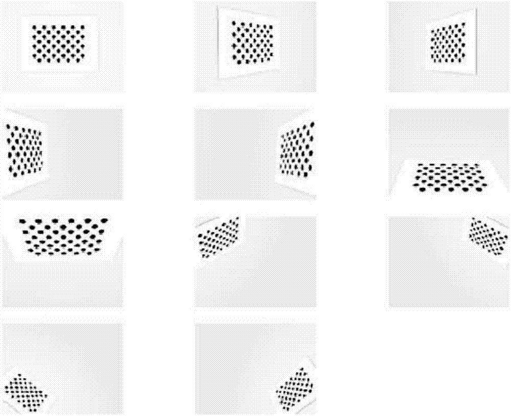
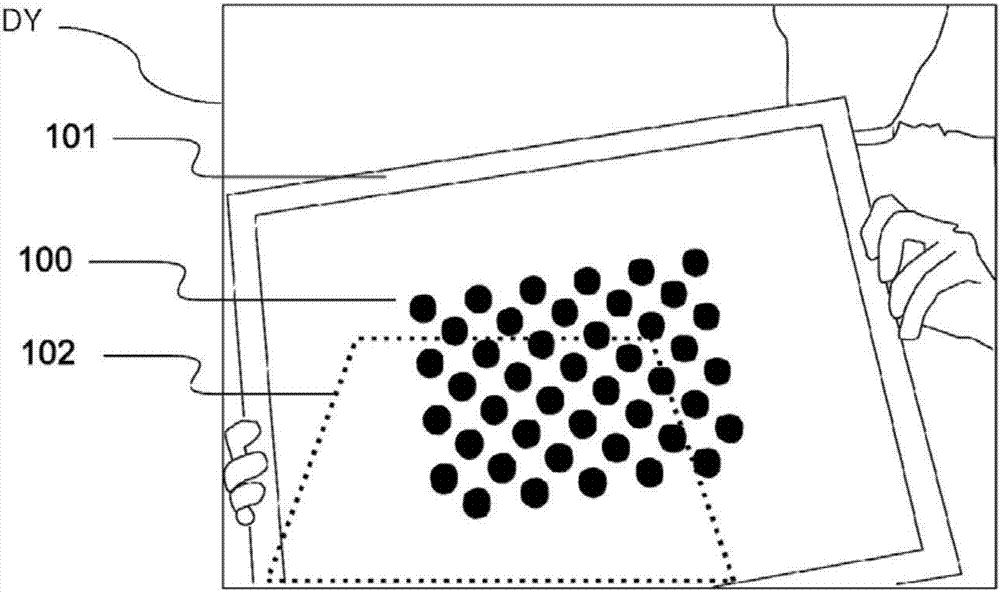
[0054] As explained above, the computer program of the present invention guides the user to place the calibration pattern in several different poses within the fiel...


PUM


Abstract

A computer-implemented method of calibrating a camera comprises the steps of: a. acquiring a video stream from said camera (CAM), and displaying it on a screen (DY); b. displaying on the screen, superimposed to the video stream, a representation of a target area (102); c. detecting a calibration pattern (100) in the video stream and periodically check whether it fits within the calibration area; d. when the calibration pattern is found to fit within the calibration area, extracting an image thereof from the video stream; said steps a. to d. being iterated a plurality of times using respectivetarget areas corresponding to different positions of a physical support (101) carrying the calibration pattern; and then e. estimating intrinsic calibration parameters of the camera by processing saidimages. A computer program product, computer-readable data-storage medium and computer system for carrying out such a method are disclosed.

Description

technical field [0001] The present invention relates to a computer-implemented method for calibrating a camera. More precisely, the invention relates to the "intrinsic" calibration of digital cameras, ie to the estimation of parameters to determine their optical response, including focal length, principal point and optional distortion parameters. Background technique [0002] The invention finds application, for example, in the field of augmented reality (AR), in which computer-generated 3D images representing virtual objects are superimposed on top of images captured by a camera. In order for the virtual image and the real image to merge in the most realistic way, the camera needs to be accurately calibrated. In fact, AR must define a virtual camera for rendering virtual 3D objects. This virtual camera must match as closely as possible the real camera used to capture the real world rendered in the background. Data provided by camera manufacturers are often not accurate e...

Claims


Application Information

Patent Timeline
Patent Type & Authority Applications(China)
IPC IPC(8): G06T7/70G06T7/13
CPCG06T2207/30208G06T2207/30244G06T7/80G06T2207/10016H04N23/63G06V20/40H04N23/64G06T7/13H04N5/44504H04N17/002
Inventor F·多加尼斯
Owner DASSAULT SYSTEMES
Why Eureka
Try Eureka