System for automatically detecting airtightness of windows and doors of building and control method

An automatic detection, building door and window technology, applied in the use of liquid/vacuum for liquid tightness measurement, by detecting the appearance of fluid at the leak point, by measuring the fluid's rate of increase and deceleration, etc. It is difficult to ensure the accuracy, uneven distribution of wind speed, etc., to achieve the effect of good social practical value, reduce human intervention, and achieve automation

Inactive Publication Date: 2018-01-05
TIANJIN UNIV
View PDF7 Cites 5 Cited by
  • Summary
  • Abstract
  • Description
  • Claims
  • Application Information

AI Technical Summary

Problems solved by technology

Some of the current detection equipment, including fans, air ducts, controllers, anemometers, differential pressure sensors, brackets, etc., are usually connected by directly inserting the anemometer into the air duct. The air flow rate is calculated, but due to the uneven distribution of wind speed on the pipe section and the influence of wind speed fluctuations, it is difficult to guarantee the accuracy of the measured flow rate; while using other types of air flow meters to directly monitor the air flow of the pipe , in order to achieve the required accuracy, the required equipment is also relatively large, and it is difficult to adapt to the requirements of portability and assembly for on-site door and window inspection

Method used


Image

  • System for automatically detecting airtightness of windows and doors of building and control method
  • System for automatically detecting airtightness of windows and doors of building and control method
  • System for automatically detecting airtightness of windows and doors of building and control method

Examples


Embodiment

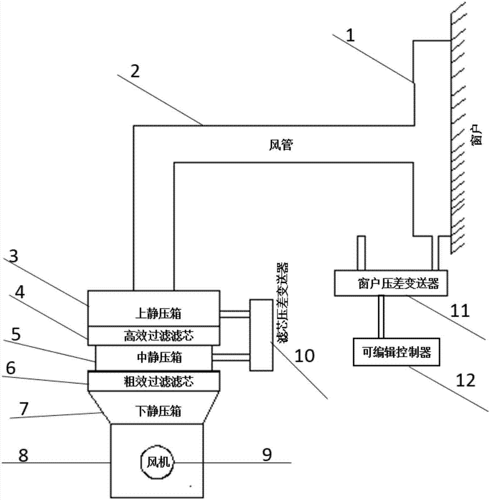
[0029] Such as figure 1 As shown, the door and window air tightness detection system mainly includes a sealing film 1, an air duct 2, an upper plenum box 3, a high-efficiency filter element 4, a middle plenum box 5, a coarse-effect filter element 6, a lower plenum box 7, Fan static pressure box 8, high pressure fan 9, filter core differential pressure transmitter 10, window differential pressure transmitter 11, editable controller 12. A high-pressure fan is housed in the fan static plenum, the air inlet of the fan static plenum communicates with the atmosphere, and the air outlet and the lower static plenum are connected by flanges; the coarse-effect filter element 6 is installed in the middle static plenum and Between the lower static pressure box; the high-efficiency filter element 4 is installed between the upper static pressure box 3 and the middle static pressure box 5, and the static pressure box and the filter element are connected by a flange, and a sealing strip is pl...


PUM


Abstract

The invention relates to a system for automatically detecting the airtightness of windows and doors of a building and a control method. A blower plenum chamber is provided with a high pressure blowertherein, and is successively provided thereon with a lower plenum chamber, a low efficient air filter element, a middle plenum chamber, a high efficient air filter element, an upper plenum chamber andan air duct. The air duct is connected to a to-be-detected window member and a sealing film so as to form an air cavity. The upper plenum chamber and the middle plenum chamber which are on two sidesof the high efficient filter element are in separate connection to a lower pressure input end and a high pressure input end of a filter element differential pressure transmitter. The window member andthe sealing film form an air cavity which is connected to a window differential pressure transmitter. According to the invention, the control method herein uses the differential difference between the upper and lower sides of the high efficient filter element to determine the air volume. Compared with conventional methods which adopt an anemometer or a flow meter to determine air volume, the method herein is much easier and more accurate. Since the rotation velocity of the blower is controlled by a programmable controller, the system and the method herein can achieve automation in the monitoring process, can cooperate with the computer to automatically record data, greatly reduce manual interference and have great social and practical value.

Description

technical field [0001] The invention relates to the field of building energy saving, and provides an on-site assembled building door and window air tightness automatic detection and control system; in particular, it relates to a building door and window air tightness automatic detection system and a control method. Background technique [0002] Air infiltration has a huge impact on indoor air quality and building energy consumption. Studies have shown that the heat consumption caused by infiltration accounts for about 1 / 3 of the total building heat consumption, including severe smog pollution in recent years, especially in winter. Indoor particulate matter such as PM2.5 seriously affects the health and safety of indoor personnel. [0003] In order to respond to the national goal of energy conservation and consumption reduction, to further develop green buildings and low-energy buildings, and to improve resource utilization, the state has made corresponding classifications on...

Claims


Application Information

Patent Timeline
IPC IPC(8): G01M3/20G01M3/26
Inventor 龙正伟成雄蕾张浩
Owner TIANJIN UNIV
Why Eureka
Try Eureka