Porous Ammonia Injection Device Used in High Temperature Reduction Zone of W Flame Boiler
A boiler and flame technology, applied in the field of porous ammonia injection devices, can solve the problems of low out-of-stock efficiency and high emissions, achieve high out-of-stock efficiency, increase the degree of contact and mixing, and reduce the amount of ammonia escape
- Summary
- Abstract
- Description
- Claims
- Application Information
AI Technical Summary
Problems solved by technology
Method used
Image
Examples
specific Embodiment approach 1
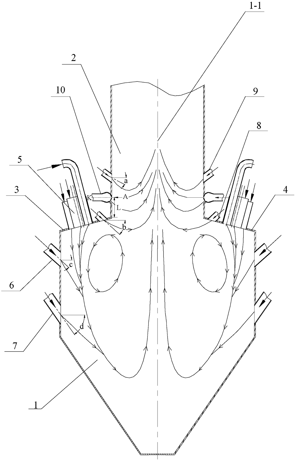
[0024] Specific implementation mode one: as Figure 1~2As shown, the porous ammonia injection device used in the high-temperature reduction zone of the W flame boiler in this embodiment, wherein the W flame boiler includes a furnace consisting of a lower furnace 1, an upper furnace 2, a front furnace arch 3 and a rear furnace arch 4, and a plurality of The swirling pulverized coal burners 5 biased by the secondary air are distributed in a line along the width direction of the furnace respectively, and the swirling pulverized coal burners 5 on the front furnace arch 3 and the rear furnace arch 4 Symmetrically arranged, the porous ammonia injection device includes a plurality of porous ammonia injection components 10, the porous ammonia injection components 10 are hollow spheres, and the upper part of the front side wall of the lower furnace 1 is sequentially arranged with a plurality of swingable exhaust air nozzles along the horizontal direction 6. The middle part of the front...
specific Embodiment approach 2
[0025] Specific implementation mode two: as figure 1 As shown, the porous ammonia injection assembly 10 of this embodiment is arranged in the area above the furnace throat and below the swingable second-stage burn-off air nozzle 9, and the central plane K of the porous ammonia injection assembly 10 reaches the front furnace arch 3 or the rear furnace arch 4 The upper edge distance L ranges from 0.5m to 2m, the angle between the central plane K of the porous ammonia injection assembly 10 and the horizontal plane is 0°, and the porous ammonia injection assembly 10 is set in one-to-one correspondence with the second-stage overburning air nozzle 9, The central planes K of the porous ammonia injection components 10 are located on the same plane. Other components and connections are the same as those in the first embodiment.
specific Embodiment approach 3
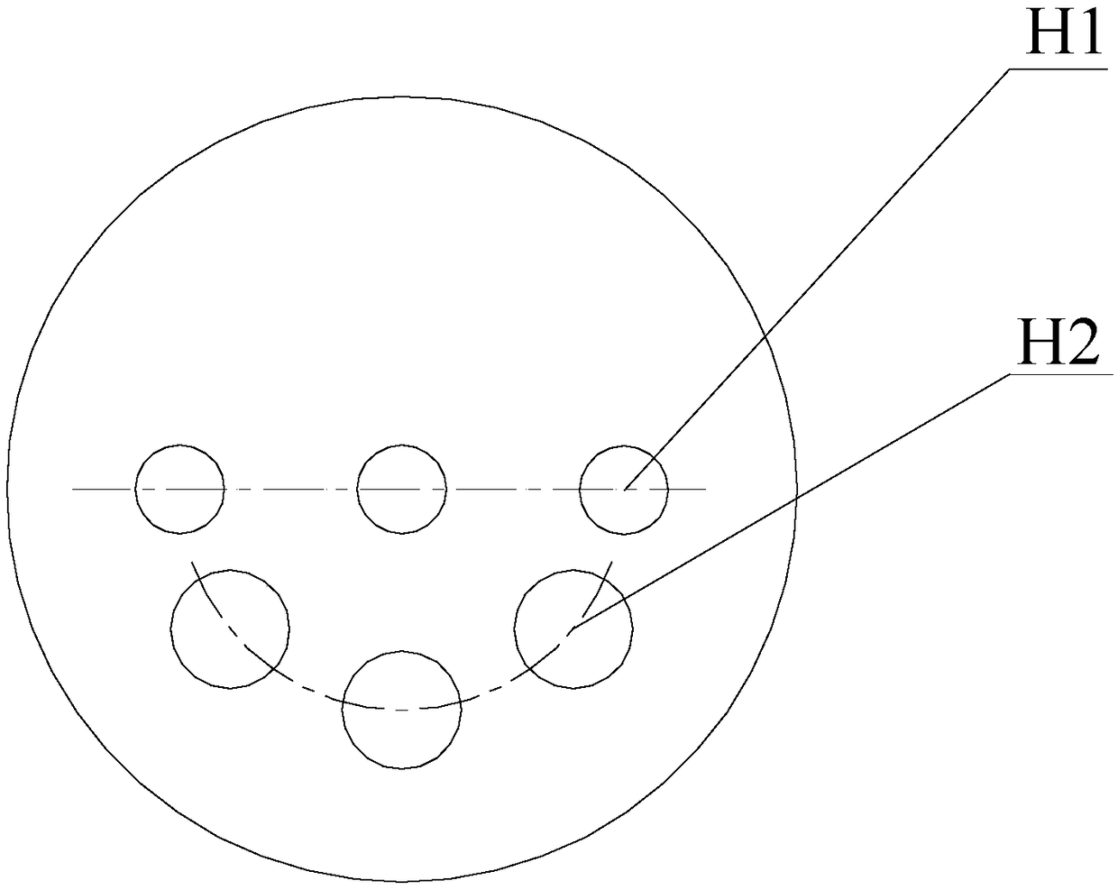
[0026] Specific implementation mode three: as figure 2 As shown, in this embodiment, the circular orifices are distributed in two layers on the hemisphere below the central plane K, the angle between the central plane of the horizontal orifice H1 of the first layer and the horizontal plane is 0°, and the center of the inclined orifice H2 of the second layer The angle between the plane and the horizontal plane is 45°. With this design, the orifices of the porous ammonia injection device are distributed in layers, and the inclined orifices and horizontal orifices realize the single-structure double-layer ammonia injection in the furnace. The ammonia sprayed from the inclined orifices is firstly mixed with the rising flue gas to realize The first layer of ammonia injection reduces NO x , the flue gas continues to rise, and soon mixes with the ammonia sprayed from the horizontal orifice, and again with the NO in the flue gas x A reduction reaction occurs, and the second layer o...
PUM
 Abstract
Description
Claims
Application Information
 - R&D
- Intellectual Property
- Life Sciences
- Materials
- Tech Scout
- Unparalleled Data Quality
- Higher Quality Content
- 60% Fewer Hallucinations
Browse by: Latest US Patents, China's latest patents, Technical Efficacy Thesaurus, Application Domain, Technology Topic, Popular Technical Reports.
© 2025 PatSnap. All rights reserved.Legal|Privacy policy|Modern Slavery Act Transparency Statement|Sitemap|About US| Contact US: help@patsnap.com


