
Continuous flow microfluidic system

A microfluidic chip, continuous technology, used in fluid mixers, instruments, nanoparticle analysis, etc., can solve the problems of expensive, expensive, and increased batch size of nanoparticles

Inactive Publication Date: 2018-01-02
THE UNIV OF BRITISH COLUMBIA
View PDF46 Cites 7 Cited by
  • Summary
  • Abstract
  • Description
  • Claims
  • Application Information

AI Technical Summary

Problems solved by technology

Thus, conventional batch processes for making nanoparticles are expensive, time-consuming, and difficult to reproduce, requiring substantial optimization of batch size increases leading to increased commercial risk
Furthermore, traditional nanoparticle manufacturing processes require nanoparticle products to come into contact with manufacturing equipment, which requires costly and time-consuming cleaning and sterilization validation, as it is not economically feasible to dispose of the equipment after each batch of manufacturing

Method used


Image

  • Continuous flow microfluidic system
  • Continuous flow microfluidic system
  • Continuous flow microfluidic system

Examples


example 1

[0346] Example 1: Use of four single microfluidic mixer devices arranged in parallel utilizing a manifold, or in a single device siRNA-lipid nanoparticles (siRNA-LNP) fabricated by four microfluidic mixers arranged in parallel.

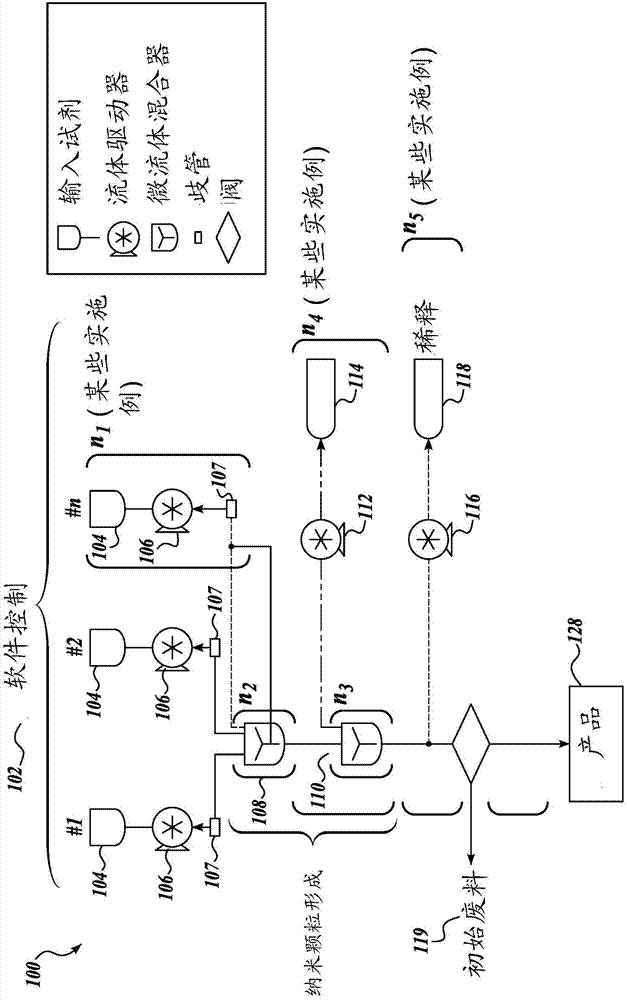
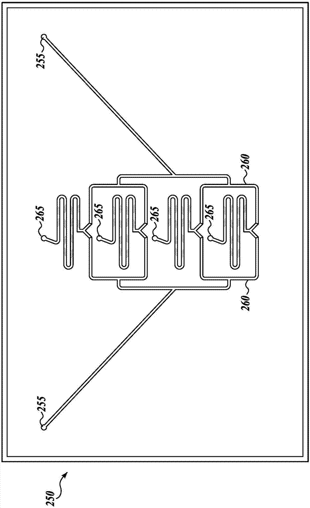
[0347] In this example, siRNA-LNP produced using four single microfluidic mixer devices in parallel utilizing a manifold was compared to siRNA-LNP produced using four microfluidic mixers arranged in parallel in a single device ( image 3 )Compare. The purpose of this example is to demonstrate that there is a method of arranging the opening-means and closing-means of a microfluidic mixer. The fluid-driven pumps were operated under the same process conditions, with the same nanoparticle-forming material, and tested for each placement method. Figure 4 The results in show that similar siRNA-LNPs were produced using both placement methods and that siRNA-LNPs were not affected by the placement method. This example significantly demonstrates the possi...

example 2

[0351] Example 2: siRNA-Lipid Nanoparticles Fabricated Using Eight Single Microfluidic Mixer Devices Arranged in Parallel Using a Manifold Rice Granules (siRNA-LNP)

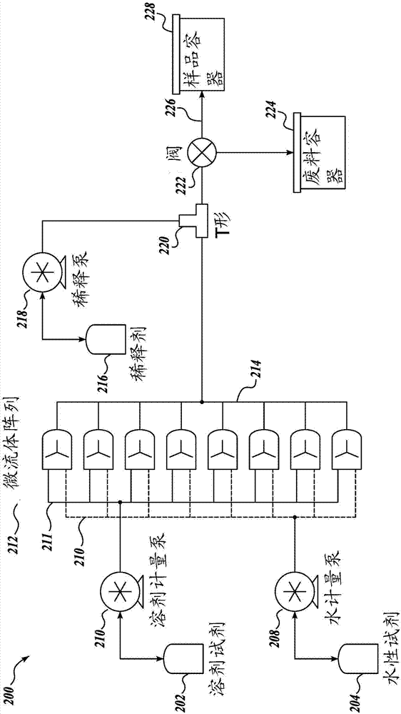
[0352] In this example, a volume of 520 mL of siRNA-LNP was generated using eight single microfluidic mixer devices arranged in parallel with an external manifold. Each mixer in the array is identical so that the process conditions for forming siRNA-LNPs in each mixer are the same. The purpose of this experiment was to demonstrate the effect of a large number of parallel mixers on the size and quality of siRNA-LNPs. This example notably demonstrates the successful utilization of a large number of microfluidic mixers used in parallel in the same system to generate high-volume batches of siRNA-LNPs using the exemplary systems disclosed herein.

[0353] Figure 5 Particle size (nm) and polydispersity index (PDI) of representative siRNA-lipid nanoparticles (siRNA-LNPs) are shown as a function of preparation volum...


PUM

PropertyMeasurementUnit
Hydrodynamic diameteraaaaaaaaaa

Abstract

The present disclosure is directed towards improved systems and methods for large-scale production of nanoparticles used for delivery of therapeutic material. The apparatus can be used to manufacturea wide array of nanoparticles containing therapeutic material including, but not limited to, lipid nanoparticles and polymer nanoparticles. In certain embodiments, continuous flow operation and parallelization of microfluidic mixers contribute to increased nanoparticle production volume.

Description

[0001] Cross References to Related Applications [0002] This application claims the benefit of US Patent Application No. 62 / 120179, filed February 24, 2015, and US Patent Application No. 62 / 275630, filed January 6, 2016, the entire contents of which are hereby incorporated by reference. Background technique [0003] Large-scale manufacturing of pharmaceutical compositions for clinical development and commercial production has historically been challenging. Techniques used in laboratories, typically for small-scale production of pharmaceuticals, are not amenable to scale-up. These challenges are exacerbated when fabricating complex drug colloidal systems such as nanoparticles. Nanoparticles comprise a variety of components including, but not limited to, lipids, polymers, low molecular weight compounds, nucleic acids, proteins, peptides, and imaging agents including inorganic molecules. Traditional processes for manufacturing nanoparticles are batch-based systems and often r...

Claims


Application Information

Patent Timeline
IPC IPC(8): G01N35/08G01N35/10
CPCG01N2035/00158G01N2015/0038B01J19/0093B01J2219/00783B01J2219/00831B01J2219/00833B01J2219/00855B01J2219/0086B01J2219/00869B01J2219/00873B01J2219/00889B01J2219/00894B01J2219/00898B01J2219/00986B01F25/43161B01F25/43172B01F25/431971B01F25/4323B01F25/4331B01F33/30B01F33/813B01F25/431B01F2101/22A61K9/1682B01J2219/00822B01J2219/00824B01J2219/00858
Inventor E·拉姆齐R·J·泰勒T·利弗A·怀尔德K·欧C·沃尔什
Owner THE UNIV OF BRITISH COLUMBIA
Learn More