Electromagnetic type energy recovery harmonic suppression device

A technology of energy recovery and harmonic suppression, applied in harmonic reduction devices, AC networks to reduce harmonics/ripples, single-network parallel feeding arrangements, etc., can solve problems such as waste, affecting transformer operation, and heat generation

Pending Publication Date: 2017-12-29
张京伦
View PDF3 Cites 0 Cited by
  • Summary
  • Abstract
  • Description
  • Claims
  • Application Information

AI Technical Summary

Problems solved by technology

[0008] Since the idea of ​​this method still uses the traditional idea of ​​canceling harmonics, the result is that the energy of harmonics is led to the transformer for consumption, which will cause new injected energy in the transformer, resulting in heat and affecting transformer operation
At the same time, since the wiring method of this patent is a large transformer that needs to increase the equivalent load capacity, it is essentially the function of a power-type isolation transformer, and its design capacity must be greater than the rated capacity of the load, which greatly increases the device. The cost and loss of the transformer, in the actual project, the investment amount may exceed the traditional passive or active harmonic suppression system, therefore, the application of this scheme is suitable for small power occasions, for large It is economically uneconomical and wasteful for capacity power users

Method used


Image

  • Electromagnetic type energy recovery harmonic suppression device
  • Electromagnetic type energy recovery harmonic suppression device
  • Electromagnetic type energy recovery harmonic suppression device

Examples


Embodiment

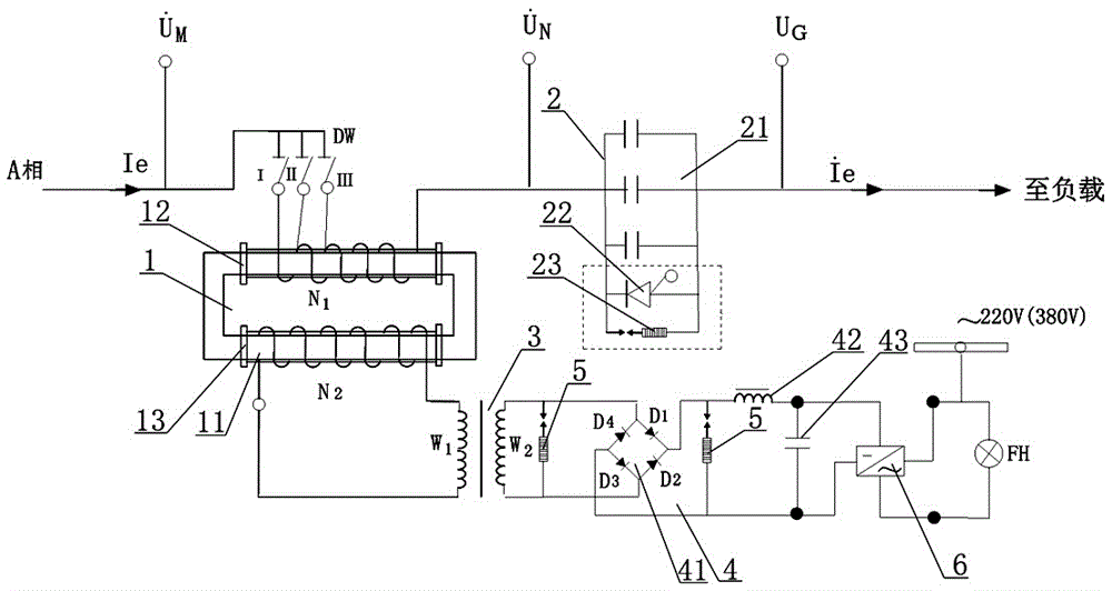
[0034] 1) Selection of current induction transformer 1:

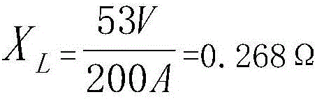
[0035] When the load current is large, it can be carried out by connecting multiple units in parallel. In the scheme, a series current induction transformer is temporarily used as an example for calculation. In the implementation of this device system, the key technology lies in the determination of the capacity of the current induction transformer 1, and the diameter of the transformer core cross-section is selected according to the transformer design principle formula Among them, S is the rated capacity kVA of the transformer, K is the coefficient, take 50~55, and the power value of the estimated harmonic in this scheme is 25% of the entire load, that is, the apparent power S, therefore, take 600÷3=200A , when the shunted load is 200A, intercept 20% of the voltage in the load as the basis, ⊿U 1 =0.2×380V=76V, so the power capacity value of the converter transformer BL-(1) is selected as:

[0036] S 1 =⊿U 1 ·I = 7...


PUM


Abstract

The present invention provides an electromagnetic type energy recovery harmonic suppression device. The device comprises a current-type induction transformer, a serial capacitor unit, a harmonic rectification transformer, a bridge rectifier unit and an automatic grid-connected inverter. The primary side winding of the current-type induction transformer is connected in series with the serial capacitor unit and then is accessed into an alternating current distribution network major loop of three-phase alternating current or single phase, the secondary side winding output end of the current-type induction transformer is connected with the input end of the harmonic rectification transformer, the output end of the harmonic rectification transformer is connected with the alternating current input end of the bridge rectifier after the voltage regulation of the harmonic rectification transformer, the output end of the bridge rectifier is connected with the automatic grid-connected inverter after shaping of the output end of the bridge rectifier through a filter reactor and a filter capacitor, and the inverter is configured to convert the multi-time harmonic energy combined and captured by the current-type induction transformer to standard electric supply and then feed the standard electric supply with the same frequency and the same phase voltage into an alternating current distribution network.

Description

technical field [0001] The invention relates to an electromagnetic energy recovery type harmonic suppression device, which is mainly used for controlling harmonics in an AC power grid and belongs to the technical field of automatic control of power grids. Background technique [0002] In recent years, due to the rapid advancement of semiconductor technology, many power electronic components with good controllability and high voltage and high current resistance have been developed. These components have been widely used in power equipment, such as motors, drives, electric arc furnaces , trams, chargers and lighting appliances, etc. Due to the nonlinear input characteristics of these devices, they generate a large amount of harmonic current during use. The existence of harmonic currents will cause some problems, such as overheating of transformers, vibration of rotating machinery, distortion of supply voltage, damage of electrical components and functional failure of medical ...

Claims


Application Information

Patent Timeline
IPC IPC(8): H02J3/01H02J3/38
CPCH02J3/01H02J3/38Y02E40/40
Inventor 张健张京伦
Owner 张京伦
Why Eureka
Try Eureka