Key-style long-distance power acquisition claw

A power card, long-distance technology, applied in the direction of circuits, electrical components, contact parts, etc., can solve the problem of low installation position, and achieve the effect of convenient power collection, convenient disassembly, convenient power on and power off

Inactive Publication Date: 2017-12-29
SHANUTEC (SHANGHAI) CO LTD
View PDF6 Cites 0 Cited by
  • Summary
  • Abstract
  • Description
  • Claims
  • Application Information

AI Technical Summary

Problems solved by technology

However, the installation position of this track socket is low, which has a certain risk of electric shock

Method used


Image

  • Key-style long-distance power acquisition claw
  • Key-style long-distance power acquisition claw
  • Key-style long-distance power acquisition claw

Examples


Embodiment 1

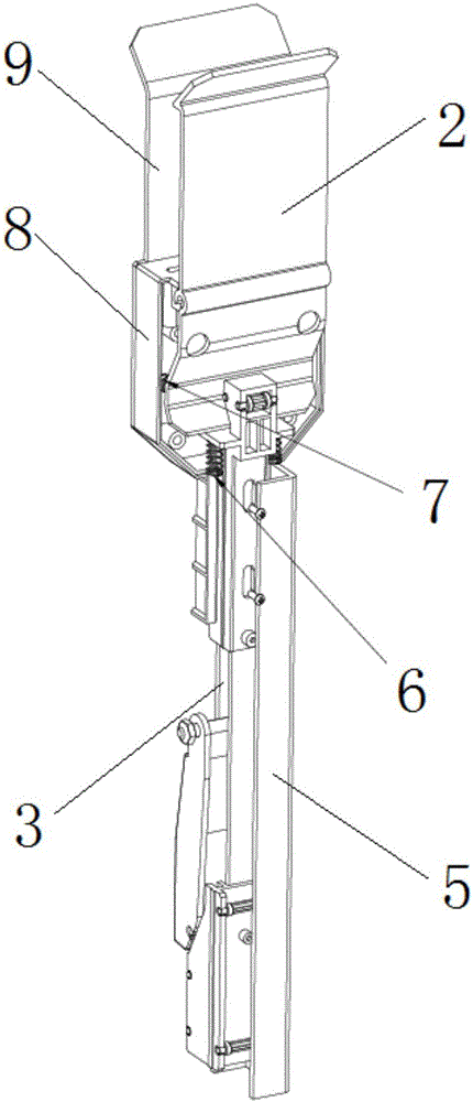
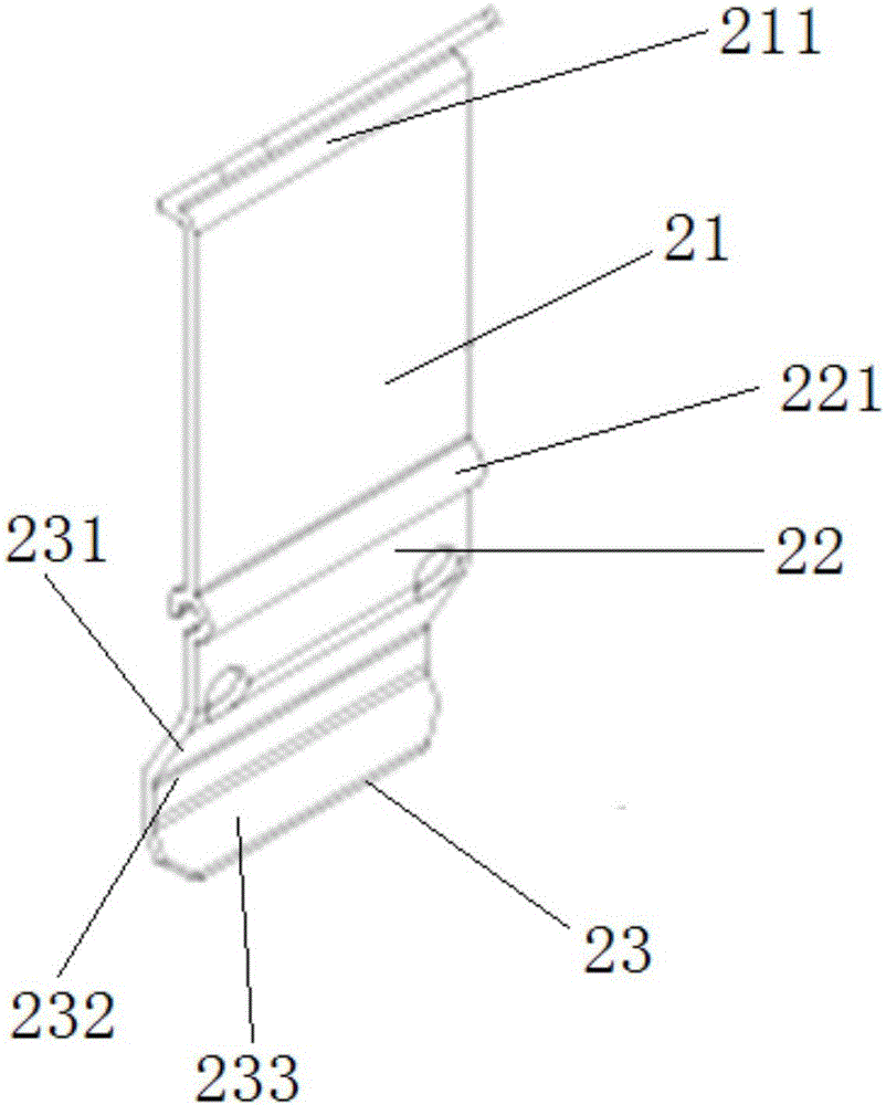
[0032] A key-type long-distance power-taking card, its structure is as follows figure 1 , figure 2 As shown, the power-taking card is connected to the power track 1, and the power track 1 is fixed on the roof. The power-taking card includes a card shell, a buckle that is arranged on the upper end of the card shell and can be opened and closed with the power track 1. Board 2 and the button unit 3 which is arranged at the lower end inside the grab shell and is used to control the rotation of the pinch plate 2. The lower end of the pinch plate 2 is connected to the socket through a wire. From the power rail 1 to the socket through the pinch plate 2 and the wire in turn, when the current needs to be disconnected, press the button unit 3 to drive the pinch plate 2 to rotate, so that the pinch plate 2 is separated from the power rail 1. In the present invention, the power track 1 is arranged on the roof to avoid danger caused by human touch, which is safer, and the opening and clo...


PUM


Abstract

The invention relates to a key-style long-distance power acquisition claw which is connected to a power track. The power track is fixed to a roof. The power acquisition claw comprises a claw housing, a pinch plate arranged at the upper end in the claw housing and detachably connected with the power track, and key units arranged at the lower end in the claw housing and used for controlling the rotation of the pinch plate. The lower end of the pinch plate is connected with a socket through a wire. When the power is normally acquired, the upper part of the pinch plate is in contact with the power track, and current is transmitted from the power track to the socket through the pinch plate and the wire successively. When the current needs to be cut off, the key unit is pressed to rotate the pinch plate to separate the pinch plate from the power track. Compared with the prior art, the key-style long-distance power acquisition claw is provided with the power track on the roof so as to avoids dangers brought by human touches, is safe, and can be controlled to be opened and closed conveniently.

Description

technical field [0001] The invention relates to the technical field of track sockets, in particular to a key-type long-distance power-taking card. Background technique [0002] Generally, the interior decoration of buildings must be wired and installed with sockets. Too many sockets will affect the aesthetics of the decoration, and too few will affect the convenience of use. At the same time, it is difficult to predict that some places will need to temporarily add sockets during decoration. , which is inconvenient, and it is very unsightly to pull the wires with a drag strip. So, there is a kind of track socket on the market at present, pass through with electric current in track exactly, then plug a socket in track, because this socket can be inserted on any length on track, so can change socket position at any time. However, the installation position of this track socket is relatively low, and there is a certain risk of electric shock. Contents of the invention [0003...

Claims


Application Information

Patent Timeline
IPC IPC(8): H01R13/02H01R13/502H01R13/629H01R25/00H01R25/14
CPCH01R25/006H01R13/02H01R13/502H01R13/629H01R25/142H01R25/145
Inventor 朱文廷林北通吴国欣张杰
Owner SHANUTEC (SHANGHAI) CO LTD
Why Eureka
Try Eureka