
Isolated and anti-interference comparison output circuit

An output circuit and anti-interference technology, which is applied in the field of comparative output circuits, can solve the problems of large signal interference, signal voltage cannot be directly used by the computer, and many stray signals, and achieve the effect of suppressing common-mode interference

Pending Publication Date: 2017-12-29
SHENZHEN HAYHON EQUIP TECH
View PDF0 Cites 0 Cited by
  • Summary
  • Abstract
  • Description
  • Claims
  • Application Information

AI Technical Summary

Problems solved by technology

[0002] In the workplace of automation equipment, because the signal voltage collected on-site cannot be directly used by the computer, the signal collected on-site is an analog signal, such as pressure sensor, temperature sensor and other signals, which are greatly disturbed and have many stray signals.

Method used


Image

  • Isolated and anti-interference comparison output circuit
  • Isolated and anti-interference comparison output circuit
  • Isolated and anti-interference comparison output circuit

Examples


Embodiment Construction

[0019] The present invention will be further described below in conjunction with the description of the drawings and specific embodiments.

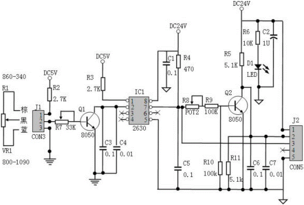
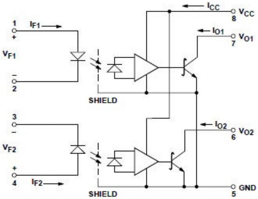
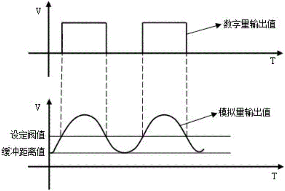
[0020] Such as Figure 1 to Figure 4 As shown, a comparison output circuit with isolation and anti-interference includes a sensor interface J1, a first-stage amplifier, a linear optocoupler integrated circuit IC1, a threshold potentiometer POT2, an output transistor Q2, and an output interface socket J2, wherein the sensor The output end of the interface J1 is connected to the input end of the one-stage amplifier, the output end of the first-stage amplifier is connected to the input end of the linear optocoupler integrated circuit IC1, and the output ends of the linear optocoupler integrated circuit IC1 are respectively It is connected with the input terminal of the threshold potentiometer POT2 and the pin 3 of the output interface socket J2, the output terminal of the threshold potentiometer POT2 is connected with the base of the output ...


PUM


Abstract

The invention provides an isolated and anti-interference comparison output circuit. The circuit comprises a sensor interface J1, a first grade amplifier, a linear optical coupler integration circuit IC1, a threshold potentiometer POT2, an output triode Q2 and an output interface socket J2. An output terminal of the sensor interface J1 is connected to an input terminal of the first grade amplifier. An output terminal of the first grade amplifier is connected to an input terminal of the linear optical coupler integration circuit IC1. An output terminal of the linear optical coupler integration circuit IC1 is connected to an input terminal of the threshold potentiometer POT2 and a pin 3 of the output interface socket J2. An output terminal of the threshold potentiometer POT2 is connected to a base electrode of the output triode Q2. The circuit has advantages that a clutter signal in a signal source can be well filtered; simultaneously a signal source is amplified; through linear optical coupler isolation, common-mode interference is restrained; and after the signal source passes through a comparison circuit, a stable voltage value is acquired.

Description

technical field [0001] The invention relates to a comparison output circuit, in particular to a comparison output circuit with isolation and anti-interference. Background technique [0002] In the workplace of automation equipment, because the signal voltage collected on-site cannot be directly used by the computer, the signal collected on-site is an analog signal, such as pressure sensor, temperature sensor and other signals, which are greatly disturbed and have many stray signals. Contents of the invention [0003] In order to solve the problems in the prior art, the invention provides a comparison output circuit with isolation and anti-interference. [0004] The present invention provides a comparison output circuit with isolation and anti-interference, including a sensor interface J1, a first-stage amplifier, a linear optocoupler integrated circuit IC1, a threshold potentiometer POT2, an output transistor Q2, and an output interface socket J2, wherein the The output e...

Claims


Application Information

Patent Timeline
Patent Type & Authority Applications(China)
IPC IPC(8): G01D3/032
CPCG01D3/032
Inventor 张电明雒文斌余怀书鲍劲松方宏丹
Owner SHENZHEN HAYHON EQUIP TECH
Learn More