
A method for shaping and implanting an optical fiber sensing network into a projectile structure

A technology of sensing network and optical fiber, applied in ammunition testing, ammunition, offensive equipment, etc., can solve problems such as complicated metal slotting process, surface damage of structure, and limited application range, so as to improve system security and reliability , high heat insulation and flame retardant properties, good environmental adaptability

Active Publication Date: 2019-06-18
BEIJING INST OF AEROSPACE CONTROL DEVICES
View PDF5 Cites 0 Cited by
  • Summary
  • Abstract
  • Description
  • Claims
  • Application Information

AI Technical Summary

Problems solved by technology

In the patent "A Method for Embedding Optical Fiber Sensors in Aircraft Cabin" with the authorization number ZL201410048814.2, the method of directly carving grooves on the metal surface of the aircraft cabin is adopted, although the shaped implantation of optical fiber sensors on the surface of the structure is realized. , but the metal slotting process is complex, the construction period is long, and there is some damage to the surface of the structure, the application range is limited

Method used


Image

  • A method for shaping and implanting an optical fiber sensing network into a projectile structure
  • A method for shaping and implanting an optical fiber sensing network into a projectile structure

Examples


Embodiment Construction

[0025] The method of the present invention will be further described in conjunction with the accompanying drawings.

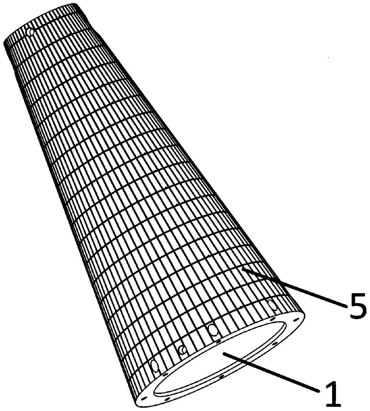
[0026] Such as figure 1 Shown, a kind of optical fiber sensory network shape-implanting method for projectile structure, comprises the following steps:

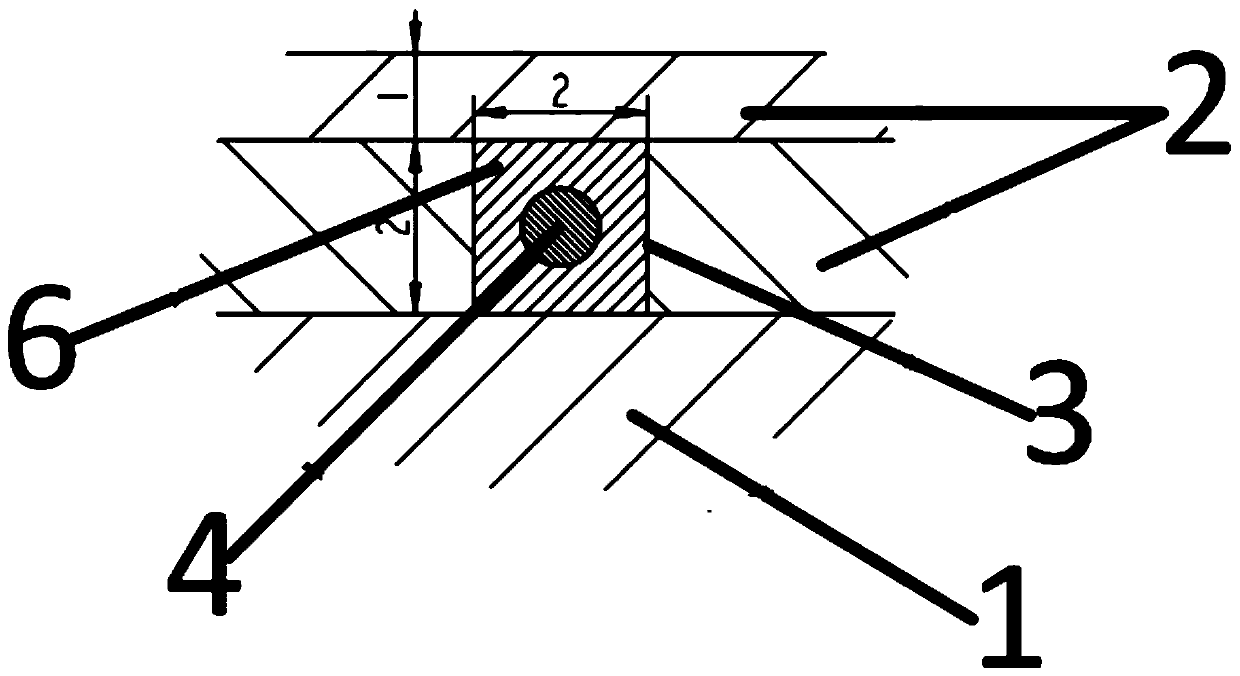
[0027] Step 1: Paste the rectangular cork board on the surface of the metal casing 1 of the missile, cut and splice it so that the cork completely covers the surface of the metal casing 1 to form a cork layer 2, and then cut off the cork layer 2 with a specific path according to the design drawing to form a structure that can accommodate the missile. The optical fiber groove 3 where the optical fiber 4 is laid.

[0028] Step 2: Lay the sensing optical fiber 4 into the fiber groove 3 one by one, the specific operation is as follows, paste double-sided tape in each fiber groove 3, the double-sided tape has a width of 2 mm and a length of 10 mm, and every 10 cm Paste a double-sided adhesive tape, lay the sensin...


PUM


Abstract

A method for embedding an optical fiber sensing network into a guided missile body structure in a shape-giving manner includes the following steps that firstly, a soft wood layer (2) is laid on the outer surface of a guided missile metal shell (1); then by means of cutting, grooves (3) capable of sufficiently containing optical fibers to be laid are formed, sensing optical fibers (4) are laid in the optical fiber grooves (3) one by one, and the optical fiber sensing network (5) equal in interval and longitudinally and transversely staggered is formed; and gaps between the optical fibers (4) and the optical fiber grooves (3) are filled with low-elasticity-modulus glue (6), and the optical fibers (4) are made to be fixed. Then, a layer of soft wood is laid on the existing soft wood layer (2) to protect the sensing optical fibers (4), so that it is prevented that when the metal shell is sleeved with a heat preventing protection layer, the optical fibers (4) are damaged. The method has the beneficial effects of being flexible in arrangement, simple in process, good in safety performance and the like, the existing structure of the structural body cannot be damaged, the method can be applied to various structural bodies, and the production efficiency can be greatly improved.

Description

technical field [0001] The invention relates to a method for shaping and implanting an optical fiber sensing network into an elastic body structure. Background technique [0002] Intelligent structure is a bionic structure system, which integrates the main structure, sensors, controllers, and drivers. It not only has a load-carrying function, but also senses and processes internal and external environmental information, and changes the structure by changing the physical properties of the structure. Respond to the environment and realize the vital signs and intelligent functions of structural health self-diagnosis, self-monitoring, self-adaptation and self-repair. At present, there are many choices of sensors that can be used in smart structures, such as piezoelectric ceramics, resistance strain wires, giant magnetostrictive films, and optical fibers. Among them, optical fiber sensors are small in size, light in weight, high in strength, and flexible Good, good flexibility, ...

Claims


Application Information

Patent Timeline
Patent Type & Authority Patents(China)
IPC IPC(8): F42B33/00F42B35/02
CPCF42B33/001F42B35/02
Inventor 王学锋王宇胡宇杨勇唐才杰朱炜炜范慧佳高腾宇
Owner BEIJING INST OF AEROSPACE CONTROL DEVICES
Learn More