Air exhausting block and die assembly
A technology of exhaust block and exhaust channel, which is applied in the field of die-casting molds, can solve the problems of low exhaust volume and efficiency, and achieve the effect of increasing the area of exhaust, increasing the efficiency of exhaust, and increasing the stroke
- Summary
- Abstract
- Description
- Claims
- Application Information
AI Technical Summary
Problems solved by technology
Method used
Image

Examples
Embodiment 1
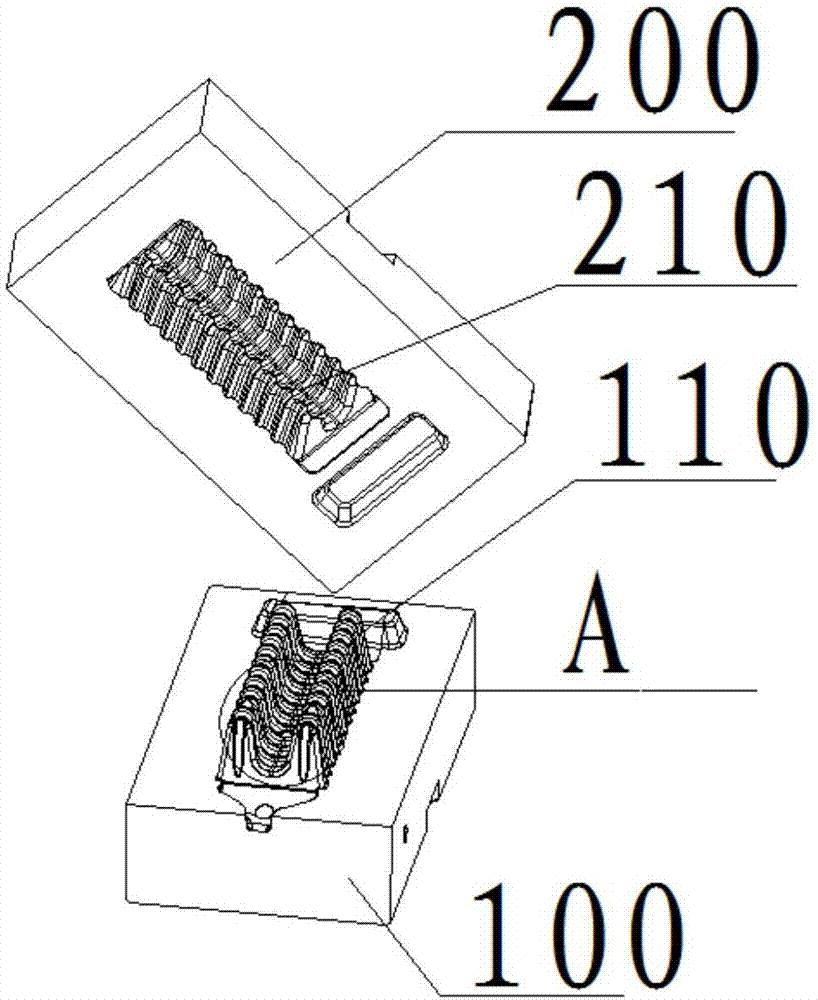
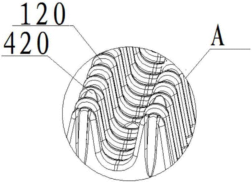
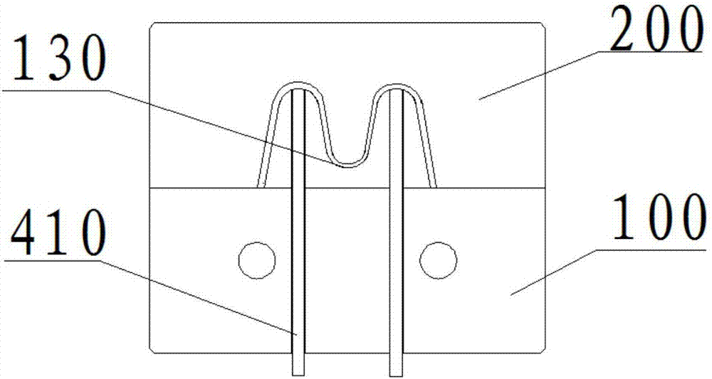
[0041] Such as Figure 1-Figure 3 As shown, the exhaust block provided by the present invention includes a first compact 100 and a second compact 200. Along the length direction of the first compact 100, the upper surface of the first compact 100 is provided with strips Protrusion 110, the second pressing block 200 is provided with a groove 210 corresponding to the strip-shaped protrusion 110, after the first pressing block 100 and the second pressing block 200 are fastened, the strip-shaped protrusion There is a gap between the protrusion 110 and the groove 210, and the gap forms an exhaust channel in the length direction of the exhaust block. Along the width direction of the strip-shaped protrusion 110, the upper surface of the strip-shaped protrusion 110 is provided with an arc-shaped portion 130, and the bending direction of the arc-shaped portion 130 is away from the upper surface of the first pressing block 100, compared to Compared with the washboard-type exhaust block...
Embodiment 2
[0055] Such as Figure 11-Figure 12 As shown, the difference from Embodiment 1 is that the heat transfer can be accelerated by increasing the layout area of the cooling channel 300 . The cooling channel 300 may include a liquid inlet channel and a liquid outlet channel arranged along the length direction of the first compact 100, and a plurality of curved channels 310 corresponding to the arc portion 130, and the curved channels 310 sandwich between the liquid inlet channel and the liquid outlet channel, and communicate with the liquid inlet channel and the liquid outlet channel respectively. The liquid inlet channel includes a plurality of liquid outlets communicating with the curved channel 310, so that the cooling liquid entering the liquid inlet channel can quickly enter the curved channel 310, and each curved channel 310 corresponds to the strip-shaped protrusion 110 , so that the molten aluminum can be rapidly solidified.
Embodiment 3
[0057] Such as Figure 13 As shown, the difference from Embodiments 1 and 2 is that the cooling channel 300 includes a liquid inlet channel and a liquid outlet channel arranged along the length direction of the first compact 100 , and the corresponding arc portion 130 A plurality of curved channels 310, in order to increase the use efficiency of the cooling liquid, the plurality of curved channels 310 are connected in sequence to form an intermediate channel, the water inlet of the intermediate channel communicates with the liquid inlet channel, and the water outlet of the intermediate channel communicates with the outlet The liquid channel is connected, and the difference from the above structure is that this structure has no branch, only one channel, which increases the flow distance of the cooling liquid, so that it can fully absorb the heat of the aluminum liquid.
[0058] The mold assembly provided by the present invention includes the above-mentioned exhaust block, the e...
PUM
 Abstract
Description
Claims
Application Information
 - Generate Ideas
- Intellectual Property
- Life Sciences
- Materials
- Tech Scout
- Unparalleled Data Quality
- Higher Quality Content
- 60% Fewer Hallucinations
Browse by: Latest US Patents, China's latest patents, Technical Efficacy Thesaurus, Application Domain, Technology Topic, Popular Technical Reports.
© 2025 PatSnap. All rights reserved.Legal|Privacy policy|Modern Slavery Act Transparency Statement|Sitemap|About US| Contact US: help@patsnap.com