A Clamping Circuit with AC Detection and DC Detection

A technology of DC detection and AC detection, which is applied in the direction of emergency protection circuit devices, circuit devices, emergency protection circuit devices, etc. used to limit overcurrent/overvoltage, and can solve false triggering, clamp circuit application restrictions, and affect chip functions, etc. problem, to achieve the effect of flexible and wide application

Active Publication Date: 2019-03-26
珠海亿智电子科技有限公司
View PDF4 Cites 0 Cited by
  • Summary
  • Abstract
  • Description
  • Claims
  • Application Information

AI Technical Summary

Problems solved by technology

The traditional clamp circuit such as figure 1 As shown, the general RC time constant is set to hundreds of nanoseconds, and its disadvantage is that it is easy to be falsely triggered by non-ESD events (such as the power-on speed of hundreds of nanoseconds); in addition, the ESD discharge FET M esd Once triggered, it is easy to pull the voltage of the PAD very low, which may affect the normal working state of the chip
Based on the above shortcomings, figure 1 The application of the clamp circuit shown is subject to certain limitations
However, in some special applications or special chip pins, such as special application requirements for fast power on or open drain pins, the traditional clamp circuit is easily triggered by mistake and affects the function of the chip

Method used


Image

  • A Clamping Circuit with AC Detection and DC Detection
  • A Clamping Circuit with AC Detection and DC Detection
  • A Clamping Circuit with AC Detection and DC Detection

Examples


Embodiment Construction

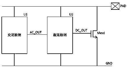
[0015] Such as figure 2 As shown, the present invention has the clamping circuit of AC detection and DC detection and comprises an AC detection module U1, a DC detection module U2, an ESD discharge FET M esd . The connections are as follows: the upper end of the AC detection module U1 is connected to the PAD, the lower end of the AC detection module U1 is connected to GND, the output terminal AC_OUT of the AC detection module U1 is connected to the input end of the DC detection module U2; the upper end of the DC detection module U2 is connected to the PAD, and the DC detection module U2 is connected to the PAD. The lower terminal of the detection module U2 is connected to GND, the input terminal of the DC detection module U2 is connected to the output terminal of the AC detection module U1, and the output terminal DC_OUT of the DC detection module U2 is connected to the ESD discharge FET M esd The grid; field effect transistor M esd The drain terminal is connected to PAD, t...


PUM


Abstract

The invention discloses a clamping circuit with alternating current detection and direct current detection functions. The clamping circuit comprises an alternating current detection module 1, a direct current detection module 2 and an ESD drain tube Mesd. When ESD happens, voltage of a node AC_OUT is low, the direct current detection module is turned on and carries out direct current detection on a voltage on a PAD. If the voltage of the PAD is higher than a set value VH, direct current detection output DC_OUT is logic high, the Mesd is turned on and an ESD current is drained. In the process of draining the ESD current, when the voltage of PAD is lower than a set safe value VL, the direct current detection output is changed into low from high, the Mesd is turned off, and ESD drainage is finished. Compared with the traditional clamping circuit, the clamping circuit disclosed by the invention has the direct current detection function and has the advantage that the clamping circuit can not be easily mis-triggered under the non-ESD condition. Besides, when the ESD triggers the clamping circuit, the voltage of the PAD can not be drained to be too low, so that the clamping circuit still can maintain a normal working condition when the PAD is attacked by the ESD, and the clamping circuit disclosed by the invention can be more flexibly and widely applied.

Description

technical field [0001] The present invention relates to the technical field of ESD (Electrostatic Discharge) in microelectronics technology, in particular to a clamp circuit that uses AC detection and DC detection to prevent non-ESD false triggering and prevent excessive discharge after ESD triggering. Technology makes the clamp circuit more flexible and more widely used. Background technique [0002] The friction between any two objects of different materials may generate static electricity. When electronic components are manufactured, produced, assembled, tested, stored, and transported, static electricity will accumulate in the human body, instruments, storage equipment, etc., and even charge will accumulate in the electronic components themselves. When the electrostatic source is in contact with other objects, there is a flow of charges, which will generate potentially destructive voltages, currents, and electromagnetic fields, which can destroy the objects in severe ca...

Claims


Application Information

Patent Timeline
Patent Type & Authority Patents(China)
IPC IPC(8): H02H9/04
CPCH02H9/04
Inventor 严智
Owner 珠海亿智电子科技有限公司
Why Eureka
Try Eureka