
Slag removing machine for PCBhole

A technology of PCB board and slag remover, applied in metal processing and other directions, can solve the problems of long reaction time and low efficiency, and achieve the effect of preventing secondary adhesion, preventing hole wall damage, and improving PCB board yield.

Active Publication Date: 2017-12-12
SUZHOU WUTONG ELECTRONICS CO LTD
View PDF12 Cites 2 Cited by
  • Summary
  • Abstract
  • Description
  • Claims
  • Application Information

AI Technical Summary

Problems solved by technology

[0002] Printed circuit board, also known as PCB board, is the support body of electronic components and the carrier of electrical connection of electronic components. The manufacturing process of PCB board is complicated. The general process is: cutting, drilling, electroless copper (PTH) And electroplating copper, pattern transfer (line), pattern electroplating (second copper) and protective tin plating, etching (SES), intermediate inspection, solder mask (SolderMask), printing characters, metal surface treatment, finished product molding, electrical testing, appearance Inspection (FQC / OQA), packaging and shipment, after the PCB board is drilled, there is a certain probability that glue residue will adhere to the PCB hole. Therefore, the PCB board needs to be desmeared before copper sinking. The PCB board is soaked in the medicine tank to remove the scum. Not only does it take a long time to react, but it also requires repeated desmear operations to completely remove the scum, which is inefficient. You can also remove the scum manually, but the efficiency is also relatively low.

Method used


Image

  • Slag removing machine for PCBhole
  • Slag removing machine for PCBhole
  • Slag removing machine for PCBhole

Examples


Embodiment Construction

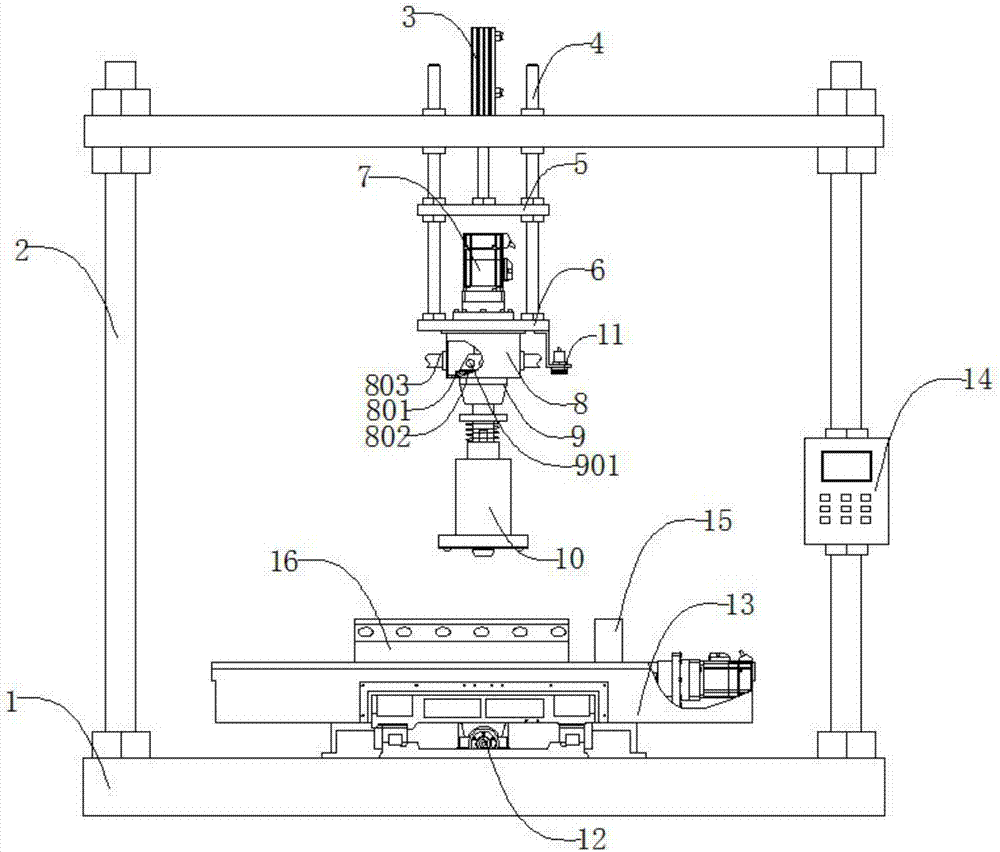
[0040] Such as figure 1 , figure 2 , image 3 , Figure 4 , Figure 5As shown, a PCB board hole slag remover includes a base 1, a door frame 2, a cylinder 3, a guide rod 4 arranged symmetrically along the cylinder 3, an upper pallet 5, a lower pallet 6, a speed regulating motor 7, Bellows 8, collet 9, pre-pressing drill mechanism 10, cross laser 11, Y-axis feed mechanism 12, X-axis feed mechanism 13, controller 14, marking block 15 with cross mark groove 1501, placement mold 16 , the door frame 2 is located at the upper end of the base 1, the door frame 2 is threaded adjacent to the base 1, the cylinder 3 is located at the upper end of the door frame 2, and the cylinder 3 is connected with the door frame 2 with threads, the The guide rod 4 runs through the door frame 2, the guide rod 4 is connected with the door frame 2 in a gap, the upper supporting plate 5 is located at the lower end of the cylinder 3 and is penetrated by the guide rod 4, the upper supporting plate 5 an...


PUM


Abstract

The invention discloses a slag removing machine for a PCB hole. The slag removing machine for the PCB hole comprises a base, a door frame, an air cylinder, guide rods, an upper bearing plate, a lower bearing plate, a speed regulating motor, an air box, a clamping head, a pre-pressing drilling tool mechanism, a cross laser, a Y axis feeding mechanism, an X axis feeding mechanism, a controller, a marking block with a cross-shaped marking groove and a placing mold, wherein the guide rods are symmetrically arranged along the air cylinder; a PCB needing to be subjected to slag removing is placed in the placing mold, the controller controls the air cylinder to push the upper bearing plate to move down, thereby pushing the pre-pressing drilling tool mechanism to move down to compress the PCB tightly, the speed adjusting motor works to drive the drilling tool mechanism to extend out slowly, and a tool bit arranged on the drilling tool mechanism smashes and removes the slag adhered to the interior of the hole. The slag removing machine is simple in structure, and can effectively remove the slag and dust adhered to the inner wall of the PCB hole, environmental protection is achieved, the dissociative waste slag can be collected to prevent secondary adhesion of the waste slag, and simultaneously pre-pressing can automatically carried out, so that the hole wall is prevented from being damaged due to deformation of the PCB, and the yield of the PCB is improved.

Description

technical field [0001] The invention relates to a mechanical device, in particular to a PCB hole slag remover. Background technique [0002] Printed circuit board, also known as PCB board, is the support body of electronic components and the carrier of electrical connection of electronic components. The manufacturing process of PCB board is complicated. The general process is: cutting, drilling, electroless copper (PTH) Copper plating and electroplating, pattern transfer (circuit), pattern electroplating (second copper) and protective tin plating, etching (SES), intermediate inspection, solder mask (SolderMask), printing characters, metal surface treatment, finished product molding, electrical testing, appearance Inspection (FQC / OQA), packaging and shipment, after the PCB board is drilled, there is a certain probability that glue residue will adhere to the PCB hole. Therefore, the PCB board needs to be desmeared before copper sinking. The PCB board is soaked in the medicine...

Claims


Application Information

Patent Timeline
IPC IPC(8): B26D7/18
CPCB26D7/18B26D7/1818B26D7/1854Y02W30/82
Inventor 沈建芳
Owner SUZHOU WUTONG ELECTRONICS CO LTD
Learn More