
Power device and system of aerial train, aerial train and aerial train system

A technology for sky trains and power units, which is applied to elevated railway systems using suspended vehicles, control devices, battery/fuel cell control devices, etc. Line operation and other problems, to achieve the effect of eliminating separate charging time, reducing charging waiting time, and improving operation and riding experience

Pending Publication Date: 2017-12-08
中建空列(北京)工程设计研究院有限公司
View PDF7 Cites 2 Cited by
  • Summary
  • Abstract
  • Description
  • Claims
  • Application Information

AI Technical Summary

Problems solved by technology

The third rail power supply method requires a long laying along the track of the sky train, which is costly, and partial power failure affects the operation of the entire line, and the anti-fault ability is weak
The lithium battery pack is used for power supply. Due to the slow charging characteristics of the lithium battery, in order to ensure the continuous operation of the sky train, it is necessary to equip a battery pack with a large capacity to ensure the continuous running distance. At the same time, it needs to be configured at the station The battery replacement device is used to replace the battery pack. Compared with the third-rail power supply method, although the anti-fault ability has been improved, the weight of the large-capacity battery is heavier, which brings unnecessary energy consumption. At the same time, the time taken for lithium battery replacement Long, and the large number of configurations of spare replaceable lithium batteries also increase the cost

Method used


Image

  • Power device and system of aerial train, aerial train and aerial train system
  • Power device and system of aerial train, aerial train and aerial train system
  • Power device and system of aerial train, aerial train and aerial train system

Examples


Embodiment Construction

[0069] Preferred embodiments of the present invention are described below with reference to the accompanying drawings. Those skilled in the art should understand that these embodiments are only used to explain the technical principles of the present invention, and are not intended to limit the protection scope of the present invention.

[0070] In addition, it should be noted that, in the description of the present invention, unless otherwise clearly specified and limited, the terms "setting", "connection" and "communication" should be understood in a broad sense, for example, it can be a fixed connection or It is a detachable connection or an integral connection; it may be a mechanical connection or an electrical connection; it may be a direct connection or an indirect connection through an intermediary, and it may be the internal communication of two components. Those skilled in the art can understand the specific meanings of the above terms in the present invention accordin...


PUM


Abstract

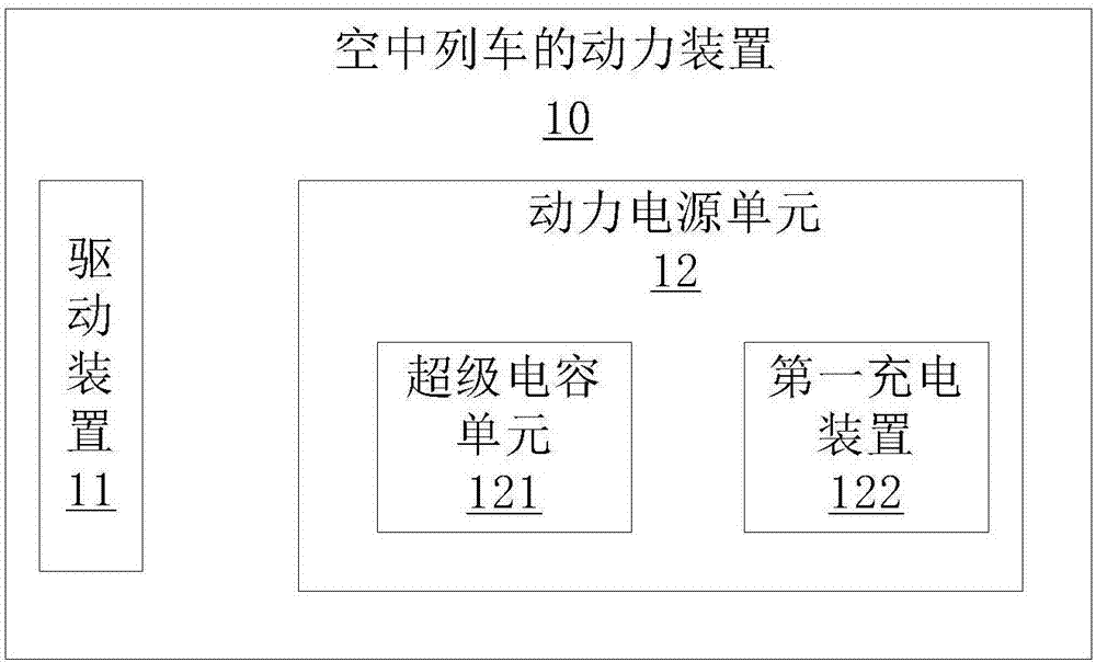
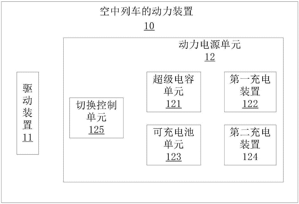
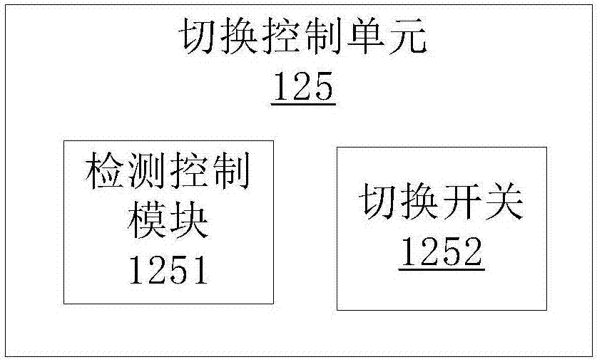
The invention belongs to the field of aerial train power, and particularly provides a power device and system of an aerial train, the aerial train and an aerial train system. The problem that in the prior art, an aerial train can not give consideration to fault resistance capacity and continuous operating capacity of a power supply system is solved. The power device of the aerial train comprises a driving device of the aerial train and a power source unit used for supplying power to the driving device. The power source unit comprises a super-capacitor unit and a first charging device. The super-capacitor unit is electrically connected with the driving device and used for driving the driving device. The power source unit further comprises a rechargeable battery unit, a second charging device and a switching control unit. The super-capacitor unit and the rechargeable battery unit are electrically connected with the driving device through alternative switching of the switching control unit. The power device of the aerial train adopts the super-capacitor unit and has the advantages of being low in weight, high in capacity, fast in charging and the like, the rechargeable battery unit is further arranged, and switching is conducted between the two power units according to situations, so that the power supplying system is safer and guaranteed.

Description

technical field [0001] The invention belongs to the field of sky train power, and specifically provides a power device and system of a sky train, a sky train and a sky train system. Background technique [0002] The rapid increase of vehicles in modern cities and the relatively congested ground traffic have seriously affected people's travel. As a result, a series of rail transit facilities such as light rail, subway, maglev train and sky rail train have appeared, forming a three-dimensional transportation network. [0003] The sky train is to hang the track on the pillars, and some train cars are suspended on the guide rail in a pendulum type, and travel along the guide rail through the traveling mechanism; some travel along the guide rail. The guide rail setting has the advantages of no road occupation, no damage to the environmental landscape, low noise, safety, low cost, short construction period and less interference to ground traffic during the construction period. ...

Claims


Application Information

Patent Timeline
Patent Type & Authority Applications(China)
IPC IPC(8): B61B3/00B60L11/00B60L11/18
CPCB61B3/00B60L50/40B60L53/12B60L53/14B60L58/10B60L2200/26B60L2240/54Y02T10/70Y02T30/00Y02T10/7072Y02T90/14
Inventor 岳渠德武长虹朱正华郑辉何晓燕
Owner 中建空列(北京)工程设计研究院有限公司
Learn More