Separator for electricity storage devices and electricity storage device using said separator
A technology for electrical storage devices and separators, applied in electrical components, electrolytic capacitors, battery pack components, etc., can solve problems such as resistance value deterioration, and achieve the effect of reducing internal resistance value, excellent resistance performance, and improving yield
- Summary
- Abstract
- Description
- Claims
- Application Information
AI Technical Summary
Problems solved by technology
Method used
Image
Examples
Embodiment 1
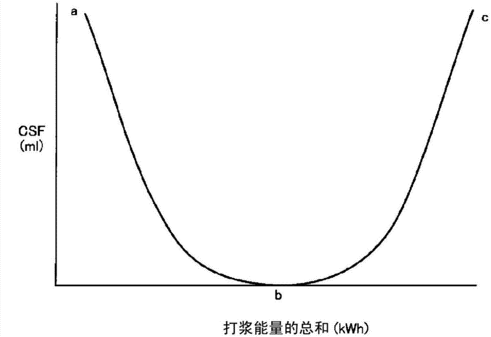
[0190] Using the following papermaking raw materials, the fourdrinier papermaking method was used to obtain a thickness of 20.0μm and a density of 0.450g / cm 3 , Tear index 15mN·m 2 / g separator, the papermaking raw material is 20% by mass of rich and strong fibers of regenerated cellulose fibers with a CSF value of 0 ml as fiber A, and the CSF value as fiber B is temporarily reduced to 0 ml (lower limit value) and then further beaten It is made by compounding 80% by mass of rich and strong fiber of regenerated cellulose fiber with increased CSF value 1ml. The separator had a CSF value of 0 ml.
[0191] Using this separator, a laminated electric double layer capacitor having a rated voltage of 2.5 V, a capacity of 3000 F, and a cell size of 55 mm×55 mm×155 mm was produced as the electric double layer capacitor of Example 1.
Embodiment 2
[0193] Using the following papermaking raw materials, the fourdrinier papermaking method was used to obtain a thickness of 10.0 μm and a density of 0.320 g / cm 3 , Tear index 14mN·m 2 / g separator, the papermaking raw material is 20% by mass of lyocell fibers of regenerated cellulose fibers having a CSF value of 0 ml as fiber A and temporarily reducing the CSF value of fiber B to 0 ml (lower limit value) 80 mass % of lyocell fibers converted into 500 ml of regenerated cellulose fibers with an increased CSF value by further beating were blended. The separator has a CSF value of 10 ml.
[0194] Using this separator, a laminated electric double layer capacitor having a rated voltage of 2.5 V, a capacity of 3000 F, and a cell size of 55 mm×55 mm×155 mm was produced as the electric double layer capacitor of Example 2.
Embodiment 3
[0196] A sheet was obtained by fourdrinier papermaking using the following papermaking raw materials: 60% by mass of regenerated cellulose fiber lyocell as fiber A having a CSF value of 350 ml, and CSF as fiber B The value was once lowered to 0 ml (lower limit value), and further beating was carried out, and 40% by mass of lyocell fibers were blended into regenerated cellulose fibers with an increased CSF value of 500 ml. Next, the sheet was calendered to obtain a thickness of 18.0 μm and a density of 0.667 g / cm 3 , Tear index 38mN·m 2 / g separator. The separator had a CSF value of 0 ml.
[0197] Using this separator, a laminated electric double layer capacitor having a rated voltage of 2.5 V, a capacity of 3000 F, and a cell size of 55 mm×55 mm×155 mm was fabricated as the electric double layer capacitor of Example 3.
PUM
| Property | Measurement | Unit |
|---|---|---|
| density | aaaaa | aaaaa |
| density | aaaaa | aaaaa |
| density | aaaaa | aaaaa |
Abstract
Description
Claims
Application Information
 - R&D
- Intellectual Property
- Life Sciences
- Materials
- Tech Scout
- Unparalleled Data Quality
- Higher Quality Content
- 60% Fewer Hallucinations
Browse by: Latest US Patents, China's latest patents, Technical Efficacy Thesaurus, Application Domain, Technology Topic, Popular Technical Reports.
© 2025 PatSnap. All rights reserved.Legal|Privacy policy|Modern Slavery Act Transparency Statement|Sitemap|About US| Contact US: help@patsnap.com


