
Shielding device for microwave plasma torch

A microwave plasma and shielding device technology, applied in the direction of plasma, electrical components, etc., can solve the problems of destroying the axis symmetry and stability of the plasma, melting and destroying the quartz cover, and reducing the service life, so as to improve the excitation efficiency and pinch Enhancement of action and prevention of burning

Active Publication Date: 2019-04-16
中控全世科技(杭州)有限公司
View PDF8 Cites 0 Cited by
  • Summary
  • Abstract
  • Description
  • Claims
  • Application Information

AI Technical Summary

Problems solved by technology

However, as the power increases, the length of the plasma increases, and the demand for oxygen shielding gas flow increases. The traditional single-tube introduction of tangential flow mode will destroy the axial symmetry of the protective layer under high airflow conditions, so that The plasma is obviously deflected to one side, which destroys the axial symmetry and stability of the plasma; since the oxygen shielding gas flows out through the gap between the outer tube and the middle tube, its exit linear velocity is limited by the cross section between the outer tube and the middle tube, The lower linear velocity cannot take away the higher heat generated by the plasma at high power, thus causing melting damage to the quartz cover at the top of the outer tube and reducing its service life; in addition, due to the increase in power, it is easy to Creates a high voltage discharge that interferes with the formation of the plasma

Method used


Image

  • Shielding device for microwave plasma torch
  • Shielding device for microwave plasma torch
  • Shielding device for microwave plasma torch

Examples


Embodiment 1

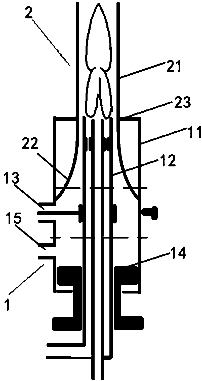
[0031] This example provides a shielding device for a microwave plasma torch, including a torch 1 for forming plasma and a shield 2 for shielding ambient gas. The structural diagrams of the torch 1 and the shield 2 are shown in figure 1 shown.

[0032] Wherein, the torch 1 includes an outer tube 11 and a middle tube 12, and the outer tube 11 is provided with a coupling antenna part 13, and the distance between the coupling antenna part 13 and the reflection end 14 is 1 / 4λ, where λ is the microwave wavelength.

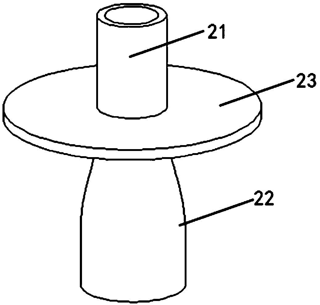
[0033] The shielding cover 2 includes a shielding tube 21, a gradient tube 22 and a sealing plate 23, and its structure is as follows: figure 2 As shown, the shielding tube 21 is a hollow straight tube, the gradient tube 22 is tapered from the bottom to the top, and the opening inner diameter of the upper end of the transition tube 22 is equal to the inner diameter of the shielding tube 21, and the upper end of the transition tube 22 is connected to the lower end of th...

Embodiment 2

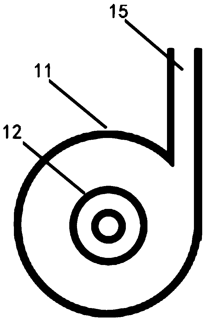
[0047] Based on Embodiment 1, the structural diagram of the shielding device provided in this example is as follows Figure 4 As shown, wherein, the difference of this example is that the distance between the coupling antenna part 13 and the torch reflection end 14 is 3 / 4λ, correspondingly, for the convenience of the antenna introduction in the coupling antenna part 13, the gradient of this example The pipe 22 is provided with a slot 221 laterally, and the structure diagram of the shielding cover 2 of this example is as follows: Figure 5 As shown, the cross-sectional view is as Image 6As shown, for the same parts of this example and the first example, please refer to the specific description of the example, and details are not described in this example.


PUM


Abstract

A shielding device of a microwave plasma torch comprises a torch tube and a shielding cover; the torch tube comprises an outer tube and an inner tube; the shielding cover comprises a shielding tube, a gradual changing tube and a seal plate; the shielding tube is a hollow tube, the inner diameter of the shielding tube is a little larger than the outer diameter of the middle tube, the gradual changing tube is in gradual contract shape with a big upper part and a small lower part, the upper end of the gradual changing tube is connected with the lower end of the shielding tube, and the outer diameter of the lower end of the gradual changing tube is the same as the inner diameter of the outer tube; the seal plate is hollow and is sleeved at the connection of the shielding tube and the gradual changing tube; and the gradual changing tube is sleeved at the middle tube, the lower end of the gradual changing tube is tangent to the inner wall of the outer tube, the seal plate is in seal connection with the outer tube, and the shielding tube is coaxial with the middle tube. The gradual changing tube enhances the motion mode of tangential spiral of oxygen shielding air, the shielding tube increase the oxygen line speed and reduce the probability of the plasma interference for the air around, and the enhanced air pinch effect enhances the stability of the plasma.

Description

technical field [0001] The invention relates to the technical field of atomic emission spectroscopy, in particular to a shielding device for a microwave plasma torch. Background technique [0002] The microwave plasma torch (MPT) is a coaxial structure of three metal tubes with one end open. The microwave energy enters the torch tube through the coaxial cable in the form of conductance / capacitance coupling. The length of the cavity is an odd multiple of 1 / 4λ. Turned into a standing wave, the plasma is formed at the open end of the torch. [0003] The length of the plasma formed by the low-power MPT is limited, and the requirements for the oxygen shielding gas flow are not high, so the introduced tangential flow can form a relatively uniform protective layer with axisymmetric distribution on the periphery of the plasma. However, as the power increases, the length of the plasma increases, and the demand for oxygen shielding gas flow increases. The traditional single-tube intr...

Claims


Application Information

Patent Timeline
Patent Type & Authority Patents(China)
IPC IPC(8): H05H1/30
CPCH05H1/30
Inventor 陈挺郭淳赖晓健刘文龙
Owner 中控全世科技(杭州)有限公司
Learn More