Paint spraying device

A technology of spraying rack and pusher device, which is applied in the field of painting, which can solve the problems of uneven surface, uneven paint thickness, and inability to move back and forth, etc., to achieve the effects of reducing waste, stable operation, and preventing dust from clogging or causing damage

Inactive Publication Date: 2017-12-01
YIWU MOYA OPTOELECTRONICS TECH CO LTD
View PDF9 Cites 0 Cited by
  • Summary
  • Abstract
  • Description
  • Claims
  • Application Information

AI Technical Summary

Problems solved by technology

Traditionally, the painting operation of panels is done manually, which is not only inefficient, but also produces more harmful gases during the painting process, which will cause great harm to the human body after being inhaled by the human body. There are also many automatic painting devices in the existing industry. , but these paint spraying devices are all sprayed in a large area, and there is a large waste when spraying paint on some narrow metal plate parts. It is easy to cause extremely uneven paint thickness, making the surface of the board uneven and poor in smoothness. Therefore, the existing paint spraying device has major disadvantages and needs to be improved.

Method used


Image

  • Paint spraying device
  • Paint spraying device
  • Paint spraying device

Examples


Embodiment Construction

[0015] All features disclosed in this specification, or steps in all methods or processes disclosed, may be combined in any manner, except for mutually exclusive features and / or steps.

[0016] Any feature disclosed in this specification (including any appended claims, abstract and drawings), unless expressly stated otherwise, may be replaced by alternative features which are equivalent or serve a similar purpose. That is, unless expressly stated otherwise, each feature is one example only of a series of equivalent or similar features.

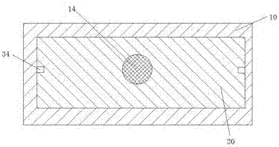
[0017] Such as Figure 1-3 As shown, a kind of spraying device of the present invention comprises a spraying rack 10, and the first sliding groove 11 with the opening facing downward is arranged in the paint spraying rack 10, and the first sliding groove 11 can be movable up and down. There is a first sliding frame 20, and the left and right sides of the first sliding frame 20 are respectively provided with a second sliding groove 200 with th...


PUM


Abstract

A paint spraying device comprises a paint spraying frame. A first slide and push groove with a through opening facing downwards is formed in the paint spraying frame. A first slide and push frame is installed in the first slide and push groove in the manner that the first slide and push frame can move up and down. Second slide and push grooves with through openings facing downwards are formed in the first slide and push frame in a left-right corresponding manner, wherein the second slide and push grooves extend in the front-back direction. Guiding and conveying grooves extending in the front-back direction are formed in the upper ends of the two side walls of each second slide and push groove. Second slide and push frames are installed in the second slide and push grooves in the manner that the second slide and push frames can move forwards and backwards. Atomization spray nozzles are fixedly installed at the lower ends of the second slide and push frames. Guiding and conveying blocks movably installed in the corresponding guiding and conveying grooves are correspondingly arranged on the left side and the right side of each second slide and push frame. Containing cavities extending in the front-back direction are formed in the second slide and push frames. Upper toothed chains are fixedly arranged in the upper end walls of the containing cavities. Lower toothed chains are fixedly arranged in the lower end walls of the containing cavities. An arrangement groove is further formed in the first slide and push frame. A second toothed chain wheel is movably installed in the arrangement groove through a second rotating rod. A first toothed chain wheel matched with the second toothed chain wheel is further movably installed in the arrangement groove through a first rotating rod.

Description

technical field [0001] The invention relates to the technical field of painting, in particular to a painting device. Background technique [0002] In some metal plate processing and production, the surface of the plate is often painted to achieve the purpose of corrosion resistance and oxidation resistance. Traditionally, the painting operation of panels is done manually, which is not only inefficient, but also produces more harmful gases during the painting process, which will cause great harm to the human body after being inhaled by the human body. There are also many automatic painting devices in the existing industry. , but these paint spraying devices are all sprayed in a large area, and there is a large waste when spraying paint on some narrow metal plate parts. It is easy to cause the thickness of the spray paint to be extremely uneven, so that the surface of the plate is uneven and the smoothness is relatively poor. Therefore, the existing paint spraying device has ...

Claims


Application Information

Patent Timeline
IPC IPC(8): B05B13/04B05B15/04
CPCB05B13/041
Inventor 吴军挺
Owner YIWU MOYA OPTOELECTRONICS TECH CO LTD
Why Eureka
Try Eureka