
System and method for integrity testing of flexible containers

Integrity, container technology, applied in the field of systems and methods for testing the integrity of flexible containers

Inactive Publication Date: 2017-11-28
MILLIPORE CORP
View PDF5 Cites 0 Cited by
  • Summary
  • Abstract
  • Description
  • Claims
  • Application Information

AI Technical Summary

Problems solved by technology

However, in many cases flexible containers may not be able to withstand this higher pressure without stretching or deforming

Method used


Image

  • System and method for integrity testing of flexible containers
  • System and method for integrity testing of flexible containers
  • System and method for integrity testing of flexible containers

Examples


Embodiment Construction

[0022] As described, conventional pressure-based integrity testing has limitations, especially as the volume of the flexible container under test becomes large, such as in excess of 200 liters.

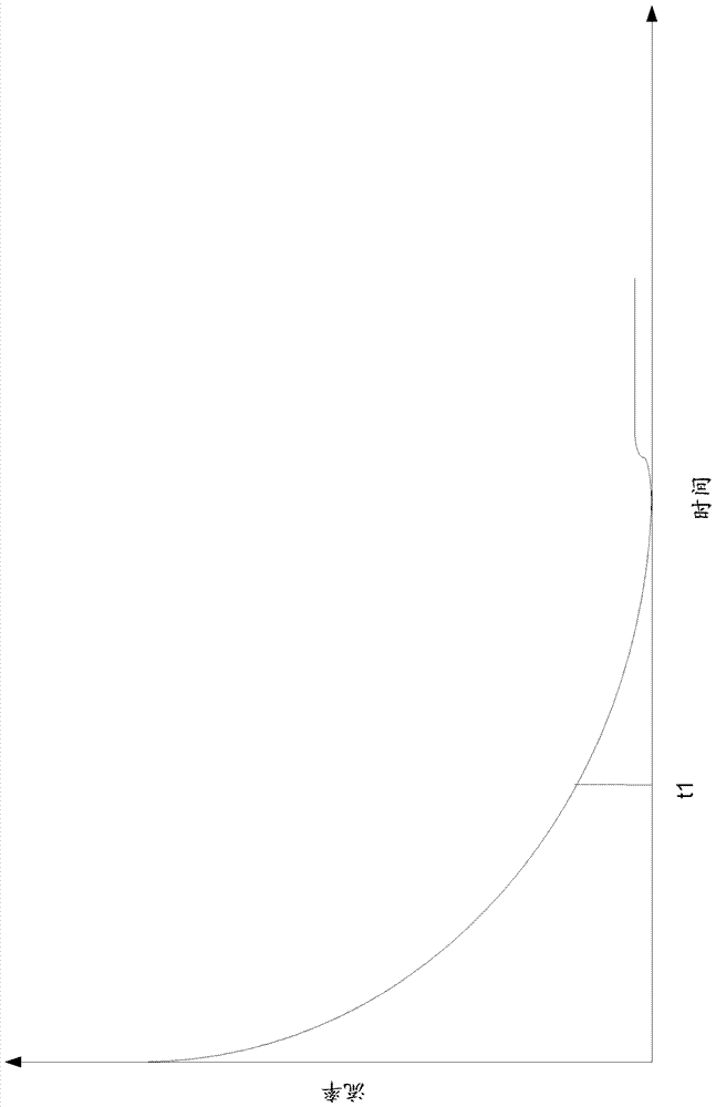
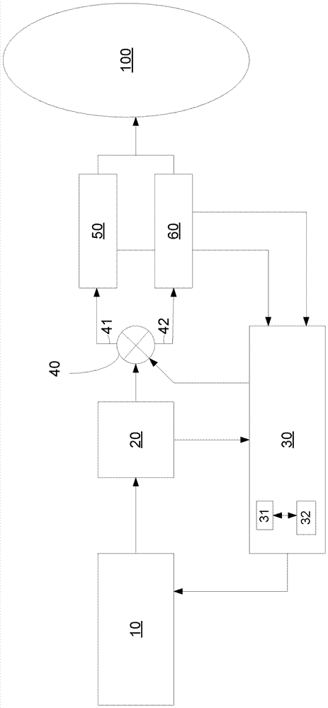
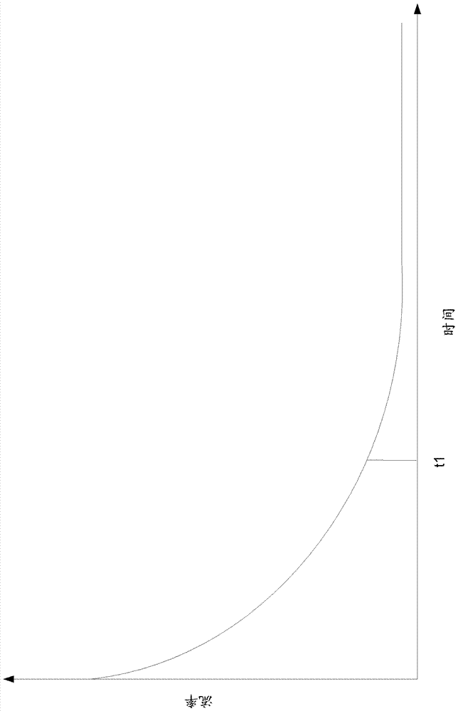
[0023] Rather than using pressure changes to determine integrity, the present systems and methods use flow rate to determine. figure 1 A system is shown that can be used to fill flexible containers and also to test their integrity.

[0024] In this embodiment there is a supply of air or another suitable fluid. Typically, the fluid used will be in gaseous form. Fluid supply 10 may be a source of compressed air or may be air conveyed through a blower, fan or other device. In various embodiments, the fluid supply 10 provides a fluid, such as air, at a variable pressure above the ambient pressure.

[0025] Fluid supply 10 communicates with sensor 20 . This sensor 20 may be a digital pressure sensor which measures the pressure of the incoming fluid from the fluid supply 10 . Controlle...


PUM


Abstract

A system and method for measuring integrity of flexible containers is disclosed. The system uses a low mass flow transducer to monitor the flow of fluid into the flexible container. Based on this flow rate, the existence of an orifice in the flexible container may be detected. The system also includes a second flow path to the flexible container to allow for faster fill times. Greater flow rates are achieve through the use of a second high mass flow transducer or a calibrated bypass path. These alternate paths allow greater flow rates until the flexible container is determined to be nearly full, at which point all flow passes with the low mass flow transducer.

Description

[0001] This application claims priority to US Provisional Application No. 62 / 127,520, filed March 3, 2015, the disclosure of which is incorporated herein by reference. Background technique [0002] Integrity testing provides a mechanism to determine whether a workpiece has any defects that would allow the undesirable transfer of particles or other matter. Integrity testing is performed extensively on filter elements. In some embodiments, the filter element is wetted and susceptible to fluid at a predetermined pressure at its inlet side. The pressure is then measured at the outlet side, and the differential pressure can be used to determine the integrity of the filter element. [0003] In other embodiments, pressure decay is used to determine the integrity of the workpiece. For example, a fluid at a predetermined pressure may be supplied to the inlet of the workpiece. As the fluid passes through the workpiece, the pressure at the inlet side decreases. The rate of pressure d...

Claims


Application Information

Patent Timeline
IPC IPC(8): G01M3/04
CPCG01F7/00G01F15/005G01M3/3218G01M3/3254G01M3/34B65D88/16B65D90/48G01M3/04
Inventor S.普罗克斯J.皮尔森斯
Owner MILLIPORE CORP
Learn More