
Efficiently cooling power distribution cabinet for electric power system

A technology for power systems and power distribution cabinets, applied in substation/distribution device housing, substation/switchgear cooling/ventilation, electrical components, etc. Efficient heat dissipation performance, ensure heat dissipation performance, and accelerate the effect of heat dissipation efficiency

Inactive Publication Date: 2017-11-24
牛翠芹
View PDF4 Cites 4 Cited by
  • Summary
  • Abstract
  • Description
  • Claims
  • Application Information

AI Technical Summary

Problems solved by technology

[0003] In order to make the circuit components inside the power distribution cabinet work in a suitable temperature environment, there are usually several cooling vents on the side panels of the power distribution cabinet for ventilation and heat dissipation, but these cooling vents are simple in design and poor in cooling effect , just passively wait for the hot air to flow out from the heat dissipation port through the opening. Due to the limited amount of hot air flowing out per unit time, the heat dissipation effect is not good. When the temperature in the external environment is also high, the temperature difference between the internal and external environments is small, resulting The air circulation is poor, not only that, after the long-term operation of the power distribution cabinet, dust and debris are usually adsorbed on the heat dissipation port, resulting in poor air circulation, and in severe cases, it will also cause blockage, which further reduces the heat dissipation performance of the power distribution cabinet

Method used


Image

  • Efficiently cooling power distribution cabinet for electric power system
  • Efficiently cooling power distribution cabinet for electric power system
  • Efficiently cooling power distribution cabinet for electric power system

Examples


Embodiment Construction

[0029] The present invention is described in further detail now in conjunction with accompanying drawing. These drawings are all simplified schematic diagrams, which only illustrate the basic structure of the present invention in a schematic manner, so they only show the configurations related to the present invention.

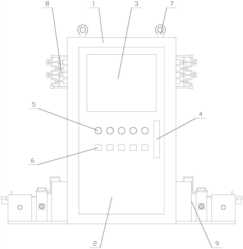
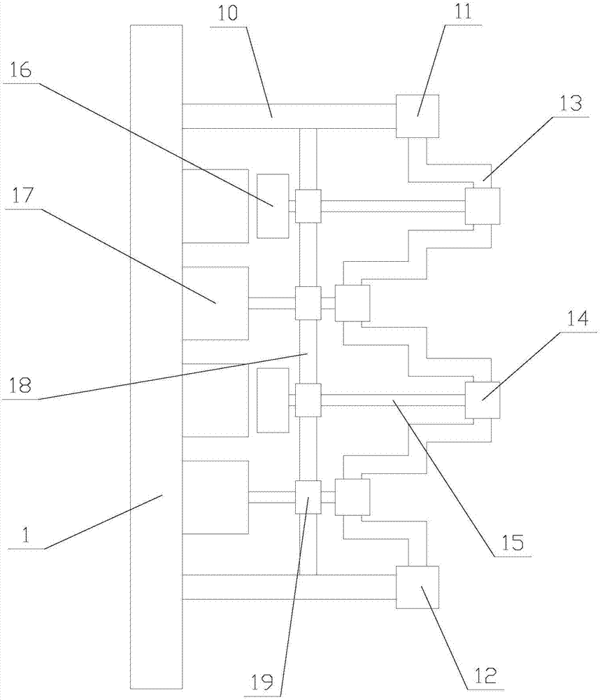
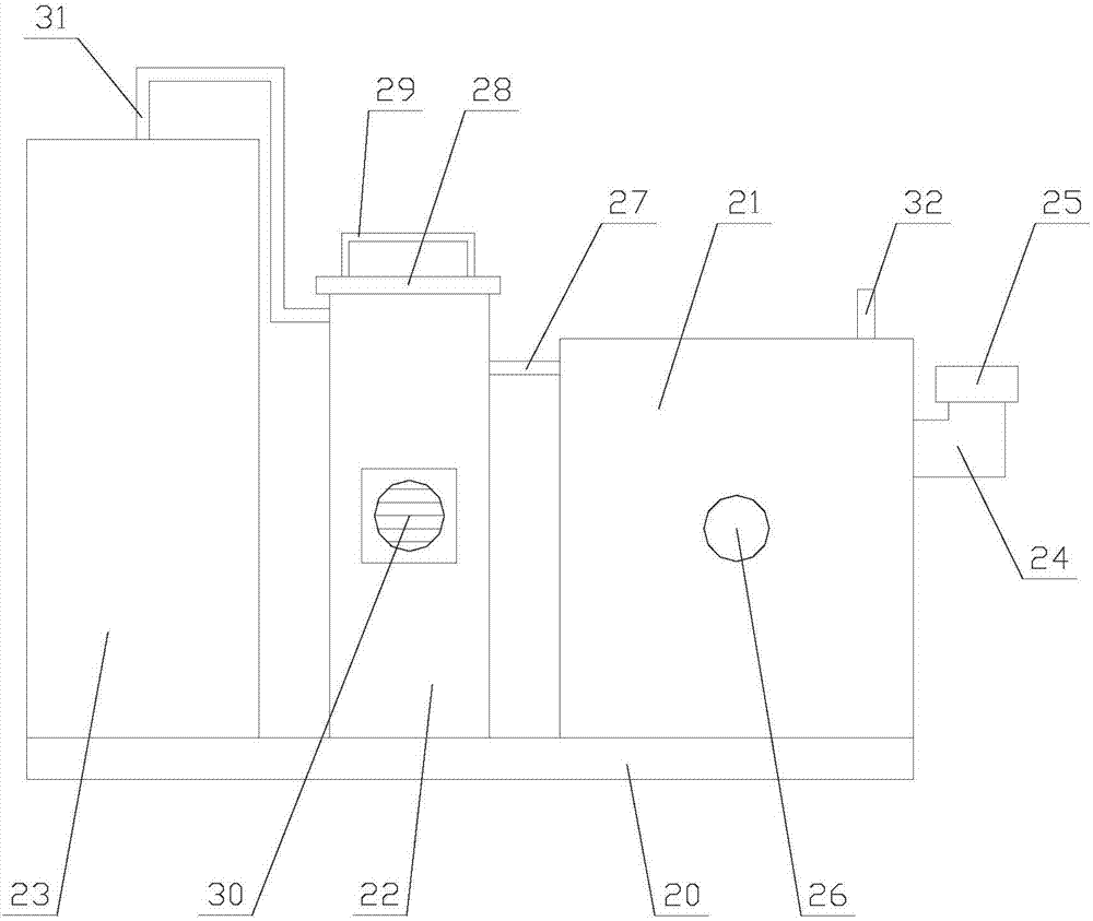
[0030] Such as Figure 1-Figure 6 As shown, a power distribution cabinet with high-efficiency heat dissipation function for power systems includes a cabinet body 1, a cabinet door 2, two dust collection mechanisms 8 and two gas transmission mechanisms 9, and the cabinet door 2 is arranged in the cabinet On the body 1, the two dust suction mechanisms 8 are respectively arranged on both sides of the cabinet body 1, and the two gas transmission mechanisms 9 are respectively arranged on both sides of the cabinet body 1 and are located below the dust suction mechanism 8. The cabinet door 2 is provided with a handle 4, a display screen 3, several indicator lights 5...


PUM


Abstract

The invention relates to a power distribution cabinet with high-efficiency heat dissipation function for power systems, which includes a cabinet body, a cabinet door, two dust collection mechanisms and two gas transmission mechanisms, and the cabinet door is provided with a handle, a display screen, and several indicators. The lamp and several control buttons, the dust suction mechanism includes the first motor, the buffer block, two poles and several dust suction units, the dust suction unit includes the frame, the collar, the connecting rod, the dust suction block and the heat dissipation pipe, and the air transmission mechanism includes Bottom plate, water storage tank, drying box, air guide box, first air pipe, cover plate, second air pipe and third air pipe, the power distribution cabinet with efficient heat dissipation function for power system absorbs the inner wall of the heat dissipation pipe through the dust suction mechanism Dust on the surface prevents clogging and affects the discharge of hot air, thereby ensuring efficient heat dissipation performance. Not only that, the dry cold air is input into the cabinet through the air transmission mechanism, which improves the heat dissipation efficiency, ensures the heat dissipation effect, and greatly improves the equipment. practicality.

Description

technical field [0001] The invention relates to the field of power equipment, in particular to a power distribution cabinet with efficient heat dissipation function for power systems. Background technique [0002] Power distribution cabinet is assembled in closed or semiclosed metal safe by electrical wiring requirement by switchgear, measuring instrument, protective device and auxiliary equipment, forms low-voltage distribution equipment. During normal operation, the circuit can be connected or disconnected by means of a manual or automatic switch, and the circuit can be cut off or alarmed by means of a protective device in case of failure or abnormal operation. The power distribution cabinet can also display various parameters in operation with the help of measuring instruments, and can also adjust some electrical parameters, and prompt or send out signals for deviations from normal working conditions through indicator lights and speakers. [0003] In order to make the ci...

Claims


Application Information

Patent Timeline
IPC IPC(8): H02B1/30H02B1/28H02B1/56
CPCH02B1/30H02B1/28H02B1/565
Inventor 牛翠芹
Owner 牛翠芹
Learn More